Method of determining the location of tip timing sensors during operation

a technology of tip timing and operation, which is applied in the direction of instruments, machines/engines, television systems, etc., can solve the problems of large rotor installation, time-consuming and laborious, and complex telemetry systems

Active Publication Date: 2015-07-16
SIEMENS ENERGY INC
View PDF4 Cites 24 Cited by
  • Summary
  • Abstract
  • Description
  • Claims
  • Application Information

AI Technical Summary

Problems solved by technology

Due to the number of strain gauges required to fully determine the vibration, the te

Method used


Image

  • Method of determining the location of tip timing sensors during operation
  • Method of determining the location of tip timing sensors during operation
  • Method of determining the location of tip timing sensors during operation

Examples


Embodiment Construction

[0015]In the following detailed description of the preferred embodiment, reference is made to the accompanying drawings that form a part hereof, and in which is shown by way of illustration, and not by way of limitation, a specific preferred embodiment in which the invention may be practiced. It is to be understood that other embodiments may be utilized and that changes may be made without departing from the spirit and scope of the present invention.

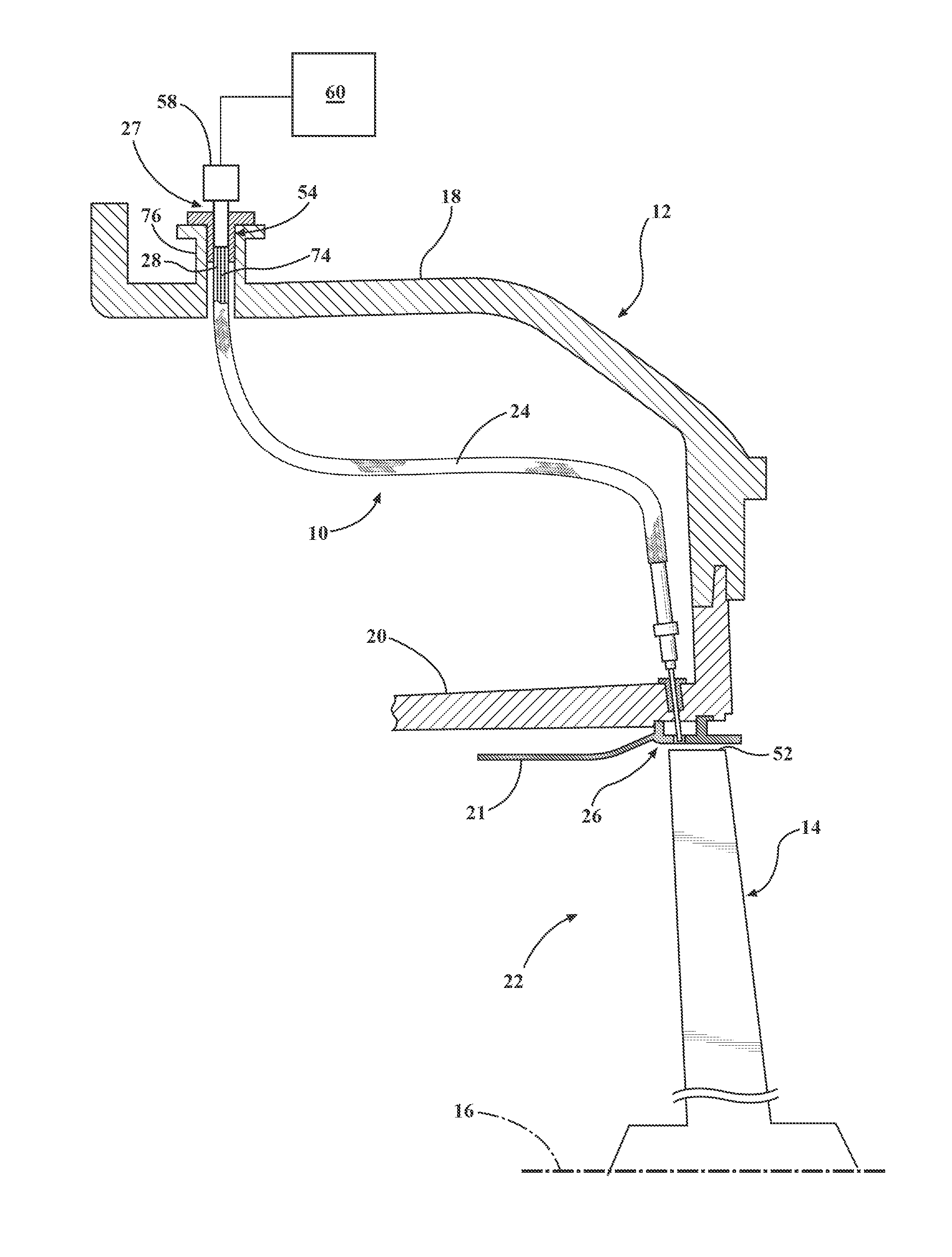
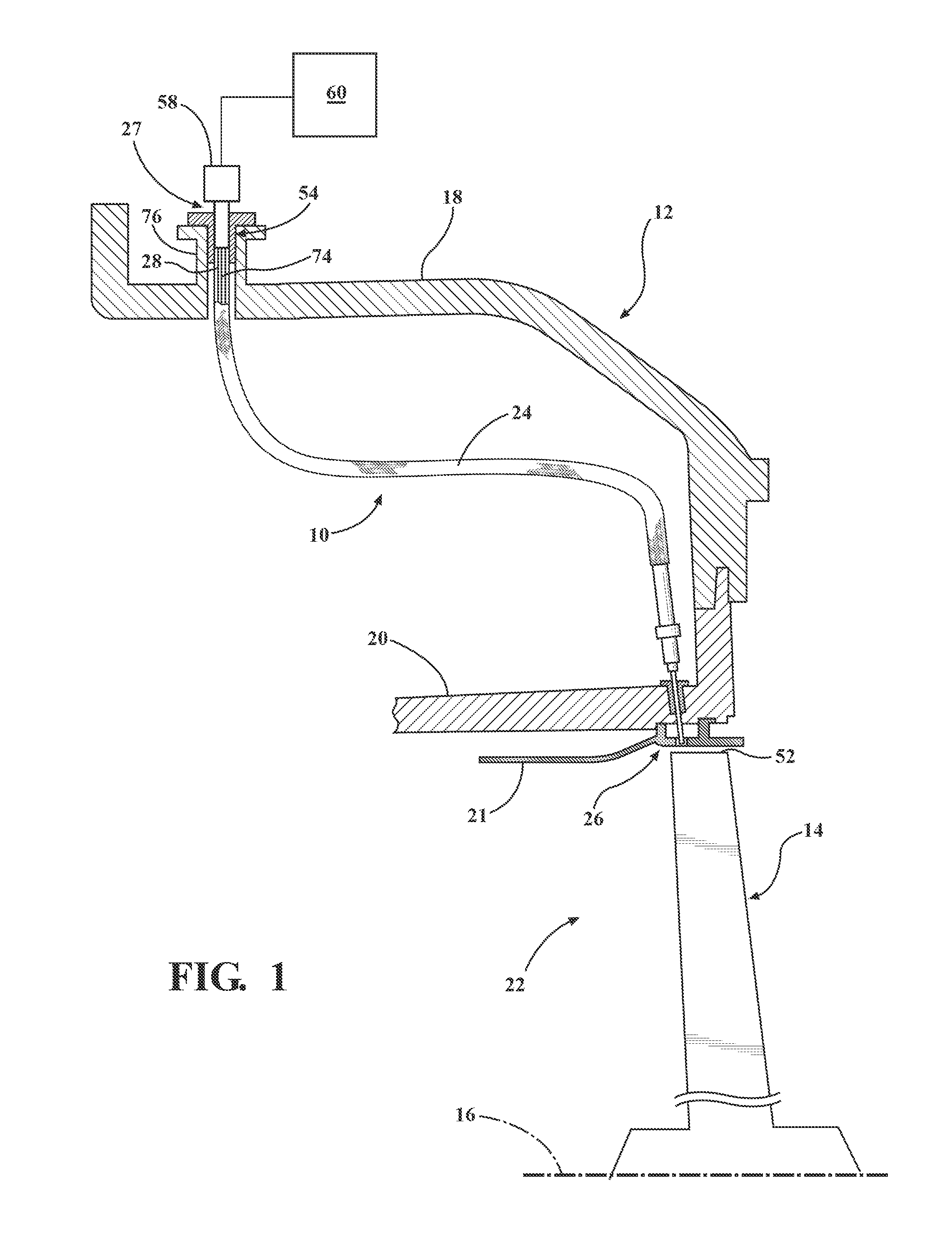
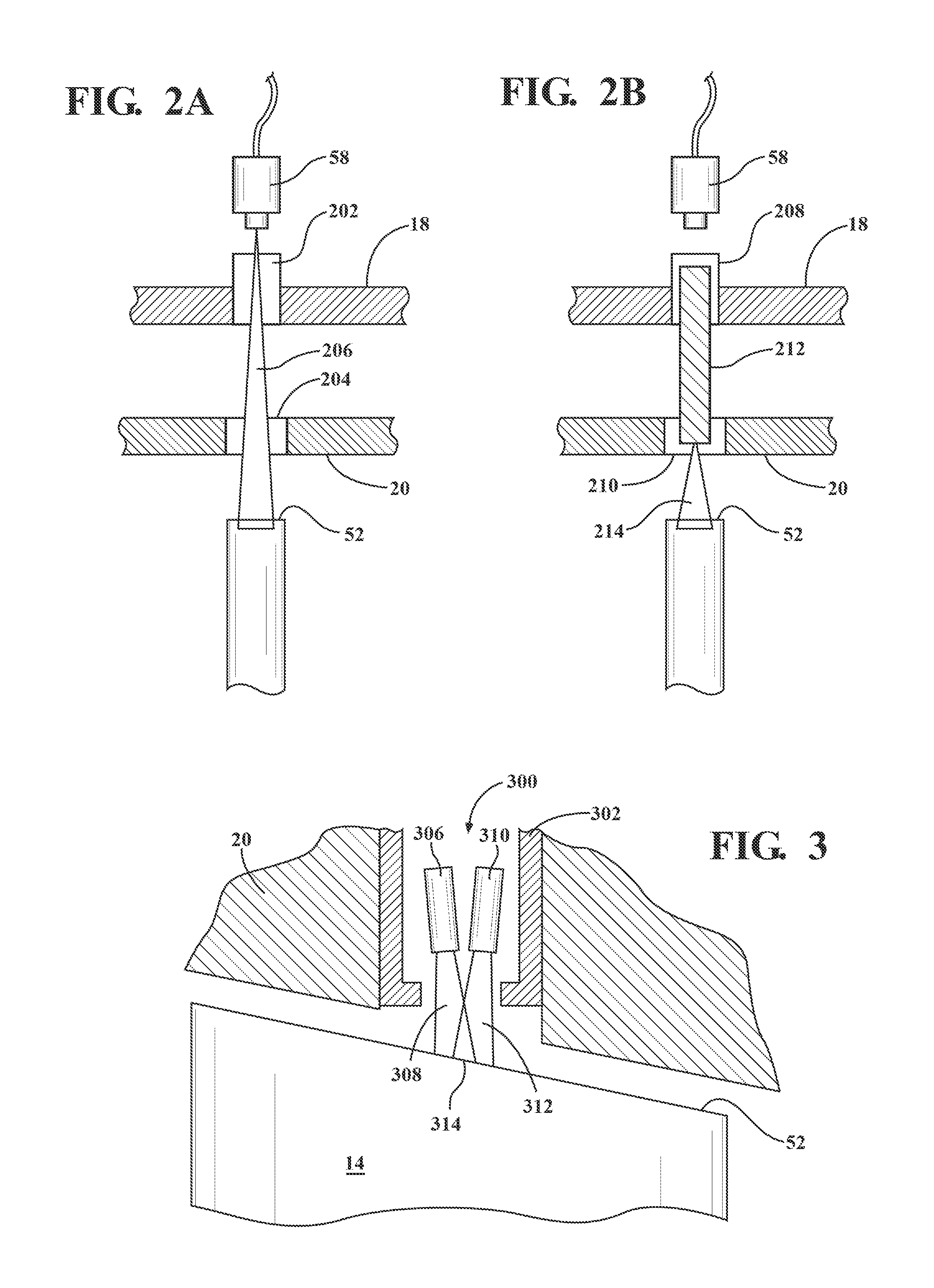
[0016]Embodiments of the present invention relate generally to a Non-Intrusive Stress Measurement (System) (NSMS) which is a method for determining dynamic blade stresses in rotating turbomachinery. NSMS is also known by the names “Blade Tip Timing” (BTT), “Arrival Time Analysis” (ATA), “Blade Vibration Monitoring” (BVM) Beruhrungslose Schanfel Schwingungsmessung (BSSM), and “Blade Health Monitoring” (BHM) NSMS uses externally mounted sensors to determine the passing times of turbomachinery blades. The passing times after conversion to d...


PUM


Abstract

A combination probe is positioned at a location in a stationary portion of a turbo machine that defines a gas flow path and is configured to detect a moving portion of the turbo machine within the gas flow path. The combination probe includes a tip timing sensor configured to sense when the moving portion is located proximate to the location of the probe, and an optical component configured to have a field of view that includes the moving portion when the moving portion is located proximate to the location of the probe. There is also an image capture device coupled to the optical component to capture an image of the field of view. The image can be used to determine the particular blade tip location within the field of view which is also the blade tip location sensed by the tip timing sensor.

Description

FIELD OF THE INVENTION[0001]The present invention relates to the field of power generating equipment and, more particularly to blade tip timing monitoring of power generating equipmentBACKGROUND OF THE INVENTION[0002]In the development of gas turbine engines, it is beneficial to measure the vibration (both amplitude and frequency) of the rotating blades. From such measurements, the induced stresses in the blades may be determined and action taken to avoid stresses which are high enough to cause damage to the blades.[0003]It is known to mount strain gauges on rotating turbine blades to provide information about the amplitudes and frequencies of vibration of the blades. Strain gauges may be provided on each blade, and connected to a telemetry system mounted on the rotor, which transmits the measurements from the rotor. Due to the number of strain gauges required to fully determine the vibration, the telemetry system can be complex, large and time consuming to install within the rotor....

Claims


Application Information

Patent Timeline
IPC IPC(8): G06T7/00H04N7/18G01M15/14G04F13/02G01B11/26G01B11/14
CPCG06T7/004G01B11/26H04N7/18G01M15/14G04F13/02G01B11/14G01H1/006G01H3/00G01H9/004G01B11/16F01D21/003G06T7/70
Inventor HATCHER, JR., CLIFFORDBRINDISI, JOSEPH M.
Owner SIEMENS ENERGY INC
Why Eureka
Try Eureka