Camera module and method for auto focusing thereof

a technology of auto focus and lens module, which is applied in the direction of camera focusing arrangement, magnetic circuit shape/form/construction, printers, etc., can solve the problems of difficult design and manufacture of voice coil motor actuators, difficult to move the lens module to the optimal position of auto focus, and complicated manufacturing process, etc., to reduce the effect of proper spring vibration

Active Publication Date: 2015-07-23
LG ELECTRONICS INC
View PDF12 Cites 62 Cited by
  • Summary
  • Abstract
  • Description
  • Claims
  • Application Information

AI Technical Summary

Benefits of technology

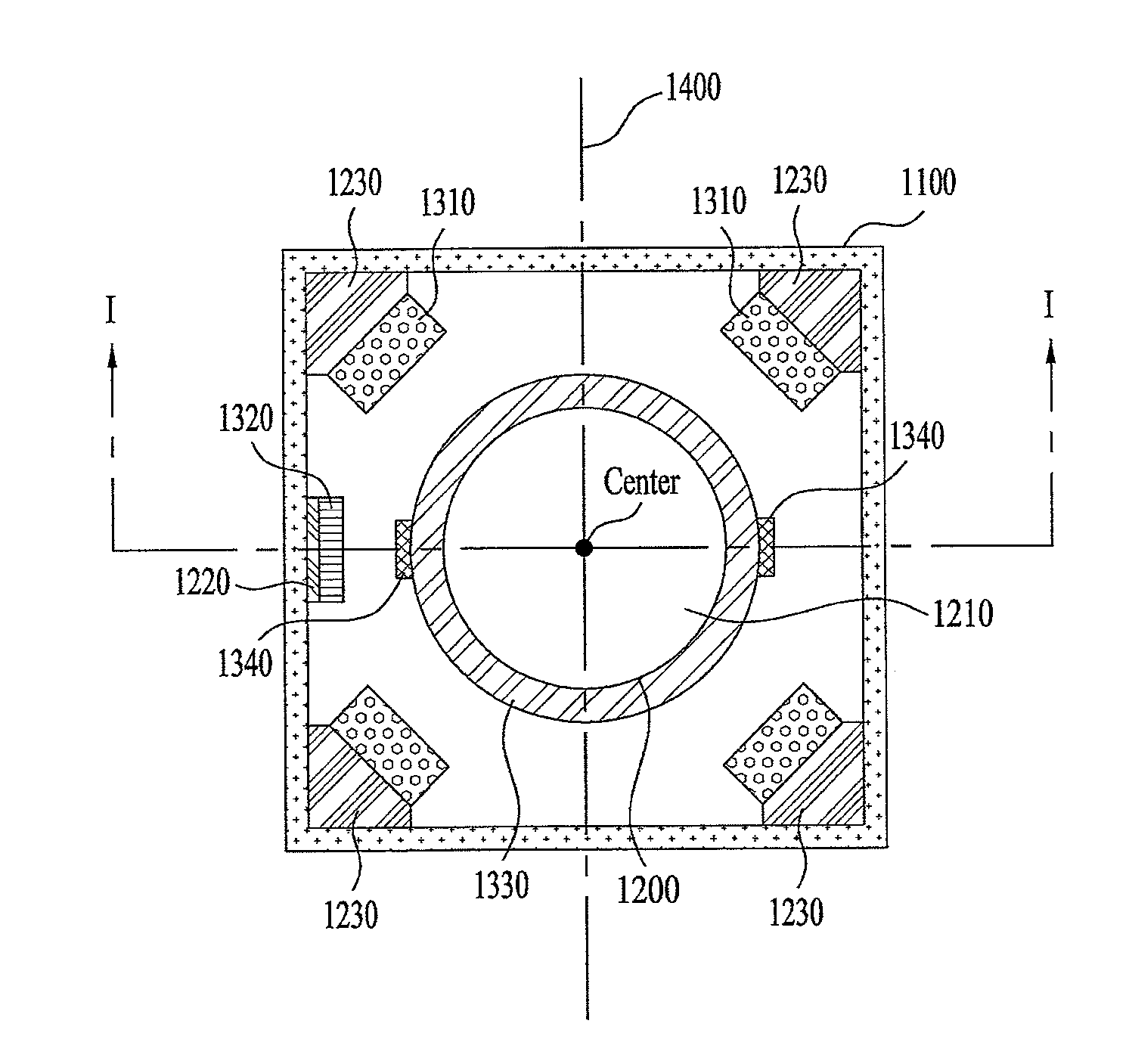
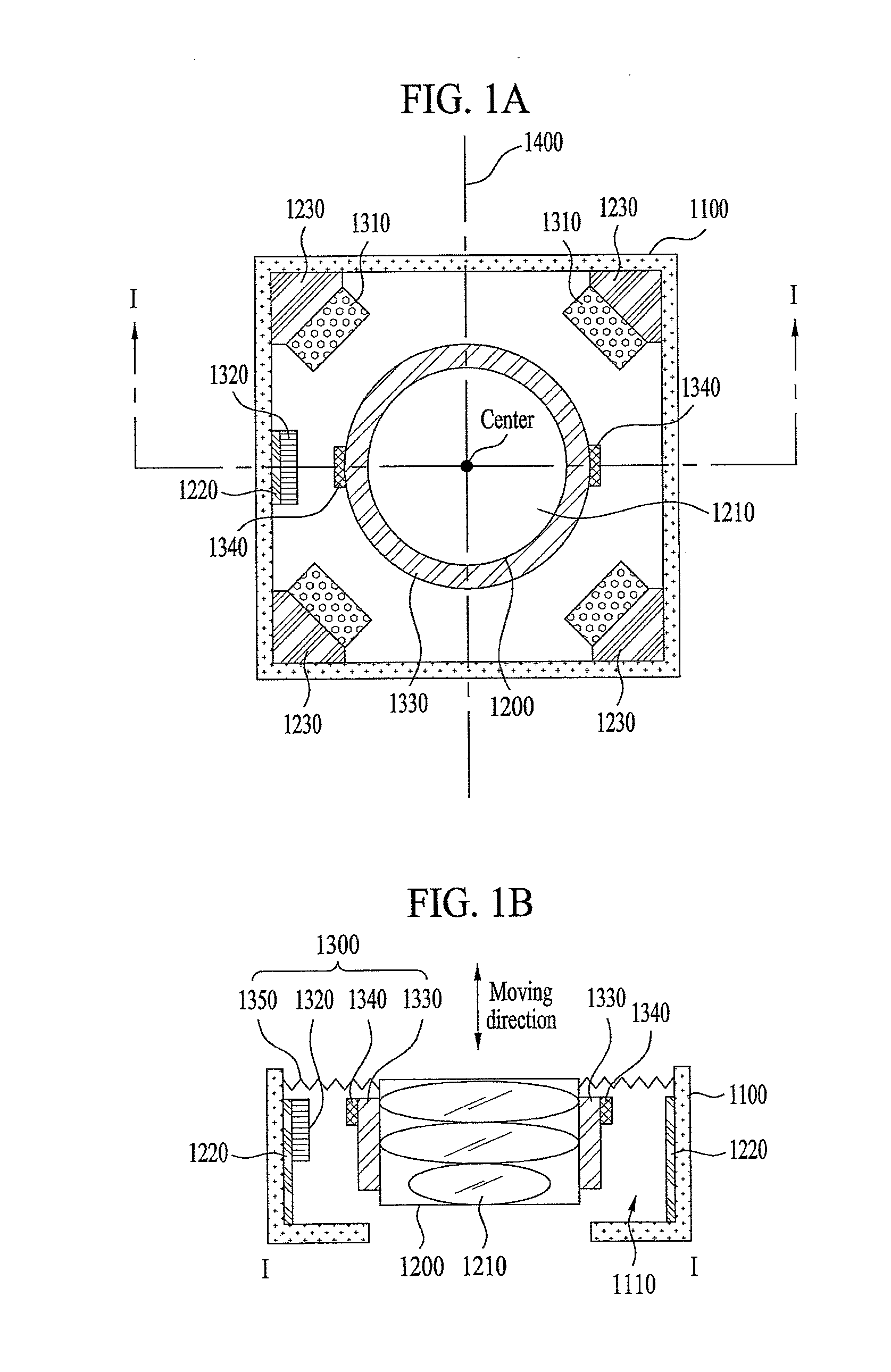
[0010]Another object of the present invention is to provide a camera module having a fixing unit in which a sensor is provided and a moving unit in which a flux distortion projection arranged to find an auto focus position rapidly and precisely, and an auto focus method thereof.
[0011]Another object of the present invention is to provide a camera module including a fixed coil arranged in a fixing unit and a moving coil arranged in a moving unit, which can find out an auto focus position rapidly and precisely based on a displacement value of a current or voltage in accordance with a distance between the fixed coil and the moving coil, and a method for auto focusing of the camera module.
[0012]A further object of the present invention is to provide a camera module including a damper arranged between a spring and a fixing unit to reduce proper vibration of the spring, and a method for auto focusing of the camera module.

Problems solved by technology

Accordingly, a manufacture process is complicated.
Accordingly, it is difficult to design and manufacture the voice coil motor actuator.
Moreover, in the voice coil motor actuator using the lens module having the sensor attached thereon, it takes quite a long time to move the lens module to an optimal position of auto focus.
There may also be auto focus position errors in the lens module.

Method used


Image

  • Camera module and method for auto focusing thereof
  • Camera module and method for auto focusing thereof
  • Camera module and method for auto focusing thereof

Examples


Embodiment Construction

[0036]Description will now be given in detail according to embodiments disclosed herein, with reference to the accompanying drawings. For the sake of brief description with reference to the drawings, the same or equivalent components may be provided with the same reference numbers, and description thereof will not be repeated. In general, a suffix such as “module” and “unit” may be used to refer to elements or components. Use of such a suffix herein is merely intended to facilitate description of the specification, and the suffix itself is not intended to give any special meaning or function.

[0037]The accompanying drawings are used to help easily understand various technical features and it should be understood that the embodiments presented herein are not limited by the accompanying drawings. As such, the present invention should be construed to extend to any alterations, equivalents and substitutes in addition to those which are particularly set out in the accompanying drawings. A...


PUM


Abstract

A camera module including a fixing unit including a hole formed therein a moving unit including at least one lens, and configured to linearly move in the hole of the fixing unit; and a driving unit configured to drive the moving unit. Further, the driving unit includes a corresponding magnet arranged in the inner surface of the hole of the fixing unit; a moving coil surrounding the outer surface of the moving unit; and a fixed coil arranged in the fixing unit and configured to receive from the moving coil a current or voltage variable based on a distance with the moving coil.

Description

CROSS-REFERENCE TO RELATED APPLICATIONS[0001]Pursuant to 35 U.S.C. §119(a), this application claims the benefit of earlier filing date and right of priority to Korean Patent Applications Nos. 10-2014-0007783, filed on Jan. 22, 2014 and 10-2014-0018974, filed on Feb. 19, 2014, the contents of which are hereby incorporated by reference herein in their entirety.BACKGROUND OF THE INVENTION[0002]1. Field of the Invention[0003]Embodiments of the present invention relate to a camera module having a voice coil motor actuator and a method for auto-focusing thereof.[0004]2. Discussion of the Related Art[0005]Mobile terminals include highly integrated diverse functions and tend to be light in weight and have a small size. In addition, camera modules mounted in mobile terminals are downsizing including smaller lenses. Further, an optical system of a camera module requires an auto focus function to make an object clearly visible. Such an auto focus function needs various types of actuators to mo...

Claims


Application Information

Patent Timeline
Patent Type & Authority Applications(United States)
IPC IPC(8): H04N5/232H04N5/225
CPCH04N5/2254H04N5/23212G03B3/10G03B2205/0069H04N23/57H04N23/55H04N23/673G02B7/08H02K1/17H02K1/34H02K41/0354
Inventor KANG, HYUNGJOOKWON, SUNGDU
Owner LG ELECTRONICS INC
Why Eureka
Try Eureka