Control device for internal combustion engine

Active Publication Date: 2015-07-30
NISSAN MOTOR CO LTD
View PDF24 Cites 10 Cited by
  • Summary
  • Abstract
  • Description
  • Claims
  • Application Information

AI Technical Summary

Benefits of technology

[0008]According to the present invention, since the EGR passage is basically in a state in which the EGR passage is filled with the EGR gas, when the operating condition is changed from the non-EGR region to the EGR region and the EGR control valve is opene

Problems solved by technology

In the case of Patent Document 1, however, for the control of the EGR, besides the EGR control valve, a component such as the intake control valve

Method used


Image

  • Control device for internal combustion engine
  • Control device for internal combustion engine
  • Control device for internal combustion engine

Examples


Embodiment Construction

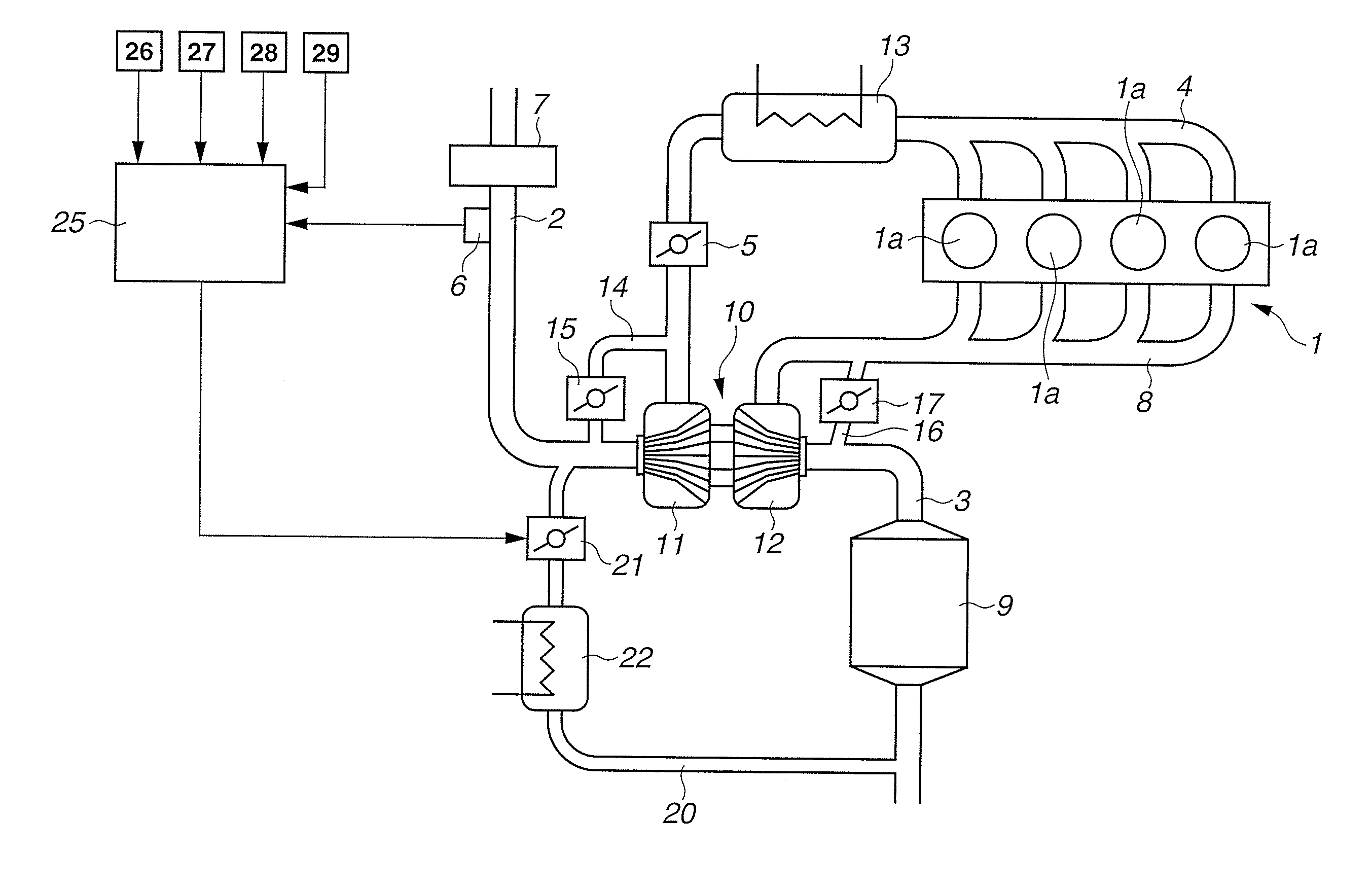
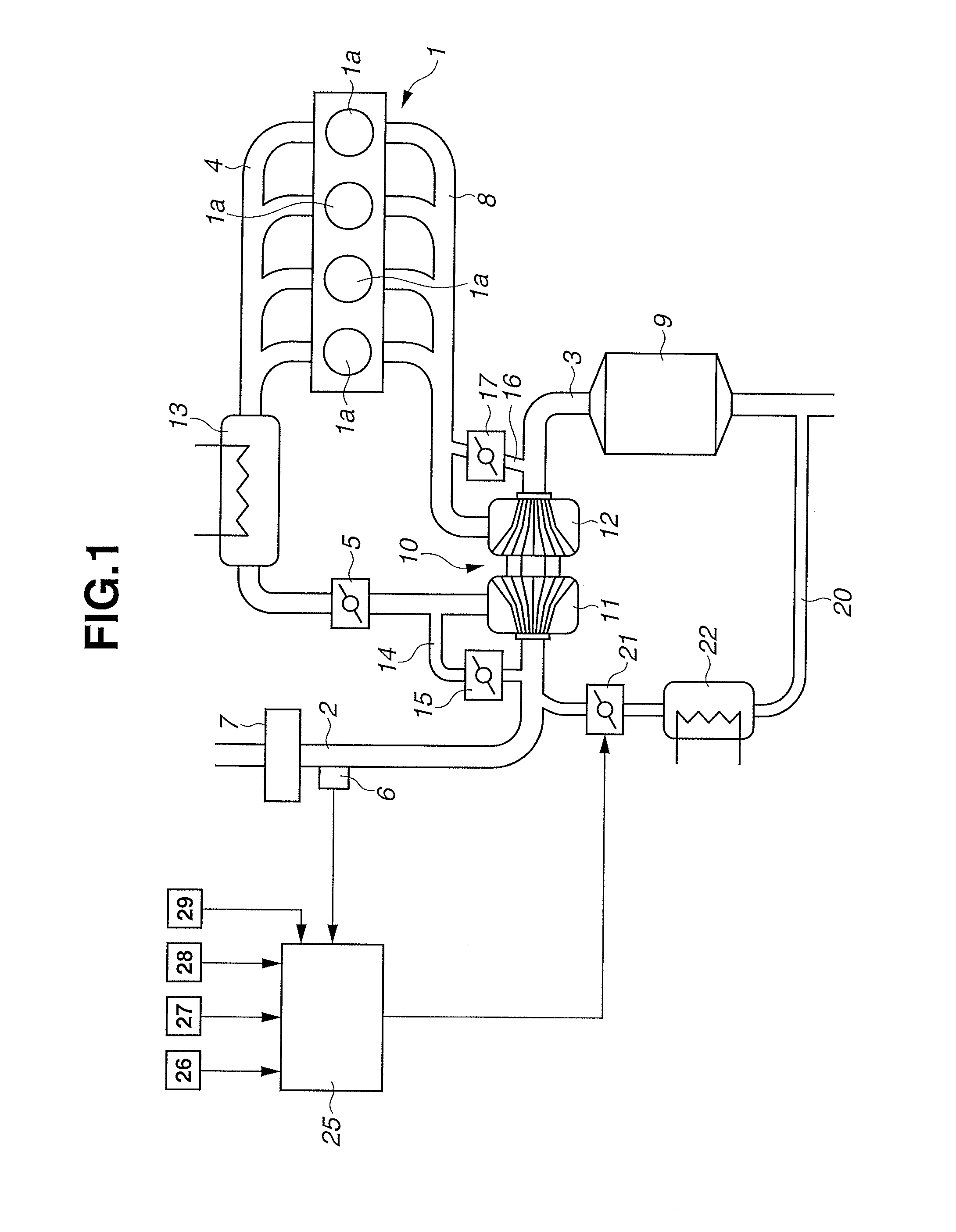
[0017]In the following description, embodiments of the present invention will be explained on the basis of the drawings. FIG. 1 is a general system block diagram of a control device of an internal combustion engine 1 to which the present invention is applied.

[0018]The internal combustion engine 1 is an engine that is mounted, as a driving source, in a vehicle such as an automobile. An intake passage 2 and an exhaust passage 3 are connected to each cylinder 1a of the internal combustion engine 1. A throttle valve 5 is provided in the intake passage 2 connecting to the internal combustion engine 1 through an intake manifold 4, also an air flow meter 6 for detecting a quantity of intake air and an air cleaner 7 are provided at an upstream side of the throttle valve 5. An exhaust catalyst 9 such as a three-way catalyst for clean-up of exhaust gas is provided in the exhaust passage 3 connecting to the internal combustion engine 1 through an exhaust manifold 8.

[0019]Further, the internal ...


PUM


Abstract

In a non-EGR region that is a light load operating region, an EGR control valve (21) is opened at a predetermined infinitesimal opening degree M that corresponds to such infinitesimal EGR ratio as not to affect an ignition timing. With this control, since an EGR passage (20) is basically in a state in which the EGR passage (20) is filled with EGR gas, when an operating condition is changed from the non-EGR region to an EGR region and the EGR control valve (21) is opened so as to gain a target EGR ratio, a desired quantity of the EGR gas is introduced into an intake passage (2) substantially at the same time as the opening of the EGR control valve (21). An actual EGR ratio can thus follow the target EGR ratio with a good response.

Description

TECHNICAL FIELD[0001]The present invention relates to a control device for an internal combustion engine that recirculates a part of exhaust gas to an upstream side of a supercharger.BACKGROUND ART[0002]There has been known a technique, in which an EGR passage connected to an exhaust passage and connected to an intake passage and an EGR control valve installed in the EGR passage are provided, and by performing EGR which introduces a part of exhaust gas into an intake system (an intake line) in accordance with an operating condition, exhaust performance and fuel economy of an internal combustion engine are improved.[0003]For instance, Patent Document 1 discloses a configuration, in which an intake control valve that is disposed in an intake pipe of each cylinder located at a downstream side of a throttle valve and changes an opening area of the intake pipe by flap motion of the intake control valve together with turning motion of a shaft is provided, and an EGR gas ejection hole form...

Claims


Application Information

Patent Timeline
IPC IPC(8): F02M25/07F02D41/00
CPCF02M25/0712F02D41/005F02D41/0077F02D41/0065F02D41/123F02D41/126F02D41/0055F02D41/0072F02M26/06F02M26/50F02M26/10F02M26/15F02M26/23Y02T10/40
Inventor TAKAKI, DAISUKE
Owner NISSAN MOTOR CO LTD
Why Eureka
Try Eureka