Solenoid valve and manufacturing method of the same

Active Publication Date: 2015-09-03
JTEKT CORP
View PDF8 Cites 7 Cited by
  • Summary
  • Abstract
  • Description
  • Claims
  • Application Information

AI Technical Summary

Benefits of technology

The invention relates to a solenoid valve that can accurately control the pressure of hydraulic fluid by adjusting the biasing force applied to a spool valve, without increasing man-hours. The technical effect is the ability to accurately adjust the valve to control pressure and minimize man-hour consumption.

Problems solved by technology

This increases man-hours for attaching the adjuster screw, which hinders improvement in productivity.

Method used


Image

  • Solenoid valve and manufacturing method of the same
  • Solenoid valve and manufacturing method of the same
  • Solenoid valve and manufacturing method of the same

Examples


Embodiment Construction

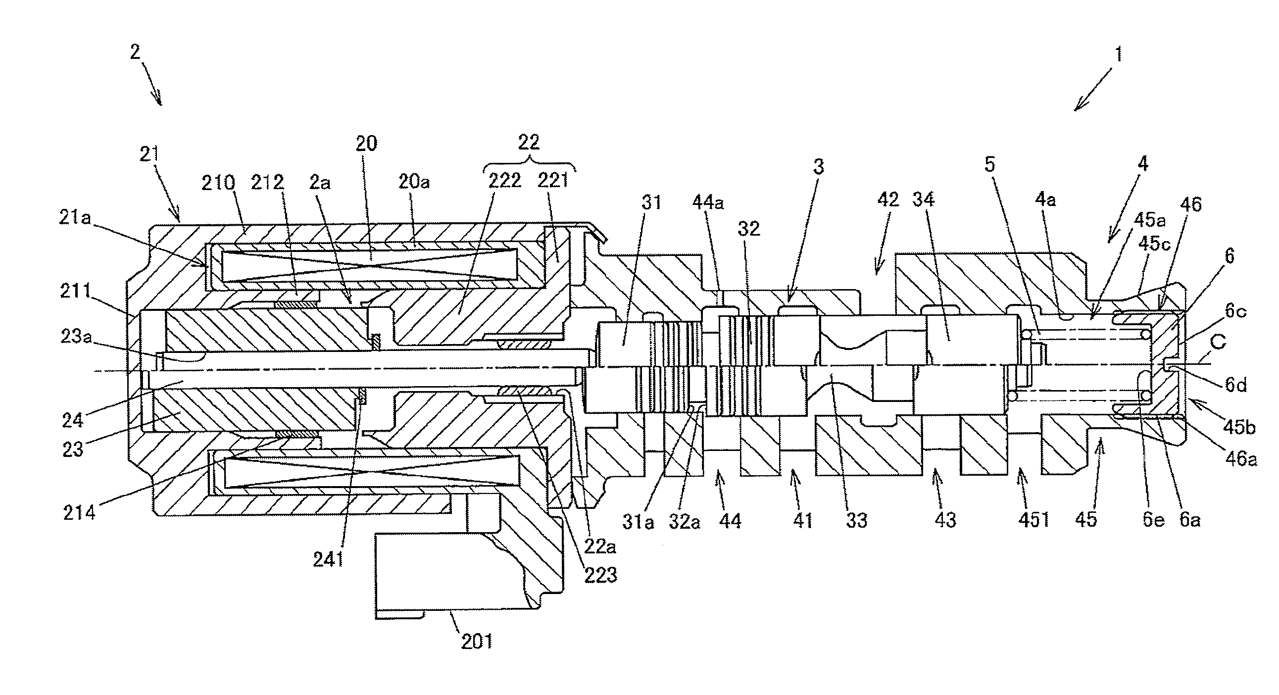
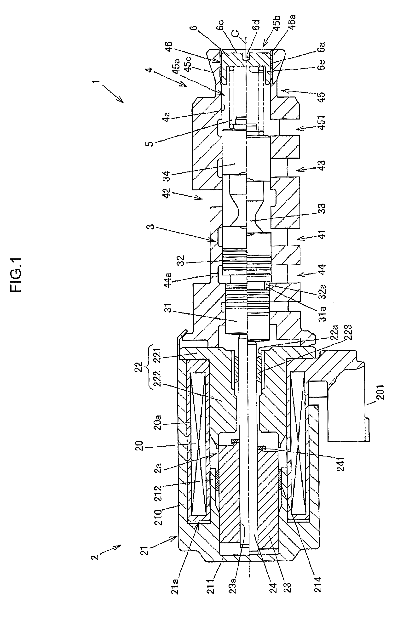
[0021]FIG. 1 is a sectional view showing a configuration example of a solenoid valve according to an embodiment of the invention. In FIG. 1, the portion above a central axis C shows the state where a current is applied to the solenoid valve, and the portion below the central axis C shows the state where no current is applied to the solenoid valve.

[0022]A solenoid valve 1 includes a solenoid portion 2, a cylindrical sleeve 4, and a spool valve 1 The solenoid portion 2 has a plunger 23 that moves in the axial direction according to a current supplied to an electro-magnetic coil 20. The sleeve 4 is placed coaxially with the plunger 23, and has an internally threaded portion 46 formed on an inner peripheral surface of its end located on the opposite side from the solenoid portion 2. The spool valve 3 is accommodated in a valve hole 4a formed in the sleeve 4, and slides on the inner surface of the sleeve 4 according to the axial movement of the plunger 23.

[0023]The solenoid valve 1 furth...


PUM

PropertyMeasurementUnit
Forceaaaaaaaaaa
Distanceaaaaaaaaaa

Abstract

A solenoid valve has a coil spring that biases a spool valve toward a solenoid portion, and an adjuster screw that is positioned to interpose the coil spring between the adjuster screw and the spool valve and that is screwed in an internally threaded portion of a sleeve so that its axial position is adjusted. The sleeve is swaged with a swaging tool etc. from an outer peripheral surface located on the outer peripheral side of the internally threaded portion of the sleeve, whereby the swaged part of the internally threaded portion is plastically deformed to the opposite side from the coil spring. The adjuster screw is thus fixed.

Description

INCORPORATION BY REFERENCE[0001]The disclosure of Japanese Patent Application No. 2014-040250 filed on Mar. 3, 2014 including the specification, drawings and abstract, is incorporated herein by reference in its entirety.BACKGROUND OF THE INVENTION[0002]1. Field of the Invention[0003]The invention relates to solenoid valves that control the pressure of hydraulic fluid, and manufacturing methods of the same.[0004]2. Description of the Related Art[0005]Conventionally, solenoid valves are known in the art which include a solenoid portion that generates an electro-magnetic force, a cylindrical sleeve having a valve hole, and a shaft-shaped spool valve that moves in the axial direction in the valve hole, and which controls the pressure of hydraulic fluid by the axial movement of the spool valve. See, e.g., Japanese Patent Application Publication No. 2012-220013 (JP 2012-220013 A).[0006]The solenoid valve described in JP 2012-220013 A includes a linear solenoid that generates an electro-ma...

Claims


Application Information

Patent Timeline
IPC IPC(8): F16K31/06B23P15/00
CPCF16K31/0613B23P15/001F16K31/0686B23P11/005F16K27/041F16K27/048Y10T29/49412
Inventor TAKANISHI, KOICHIMURAKAMI, TOSHIOFUJITA, KAORIONO, ITSUKI
Owner JTEKT CORP
Why Eureka
Try Eureka