Radio-frequency oscillation circuit

a radio-frequency oscillation and circuit technology, applied in the field of radio-frequency oscillation circuits, can solve the problems of complex control, deviating from the optimal state of the impedance matching, and affecting the operation of the radio-frequency oscillation, so as to achieve no deterioration of frequency characteristics, no increase in the output capacitance of the switching element, and low cost

Active Publication Date: 2015-09-03
SHIMADZU CORP
View PDF5 Cites 3 Cited by
  • Summary
  • Abstract
  • Description
  • Claims
  • Application Information

AI Technical Summary

Benefits of technology

[0022]The radio-frequency oscillation circuit according to the present invention does not require any DC bias circuit for applying a gradually increasing DC bias voltage to the control terminal of the switching element. Accordingly, there is no possibility that the switching element will become completely turned on by an excessively high DC bias voltage and eventually damaged. Therefore, the oscillation can be started in a stable manner. Furthermore, the radio-frequency oscillation circuit according to the present invention can be produced at a low cost, since it requires only one starter regardless of whether the switching circuit is a half-bridge drive circuit or a full-bridge drive circuit.
[0023]Furthermore, the radio-frequency oscillation circuit according to the present invention requires no switching element dedicated to startup provided parallel to the main switching element, so that there will be no increase in the output capacitance of the switching element and consequently no deterioration of the frequency characteristics. Therefore, an adequate amplitude of oscillation can be achieved even if the resonant frequency is high.

Problems solved by technology

Such a change in the impedance of the induction coil leads to a change in the load impedance seen from the radio-frequency power source, causing the impedance matching to deviate from the optimum state.
However, if the DC bias voltage is increased to an excessively high level, the switching element will be completely turned on and will allow a considerable amount of current to pass through, which may possibly damage the element.
However, since those properties considerably vary from one element to another, a complex control is needed to start the radio-frequency oscillation in a stable manner.
Furthermore, two of the four DC bias circuits must be a circuit floated from the ground potential, which means the device cost will be considerably high.
However, connecting the switching element dedicated to startup parallel to the main switching element causes an equivalent increase in the output capacitance of the switching elements.
Since the frequency characteristics of a switching element significantly depends on its output capacitance, the increase in the output capacitance deteriorates the frequency characteristics and lower the gain in the radio-frequency range, making it difficult to ensure an adequate amplitude of oscillation.

Method used


Image

  • Radio-frequency oscillation circuit
  • Radio-frequency oscillation circuit
  • Radio-frequency oscillation circuit

Examples


Embodiment Construction

[0028]As one embodiment of the present invention, a radio-frequency oscillation circuit used for plasma generation in an ICP emission spectrometer is hereinafter described with reference to the attached drawings.

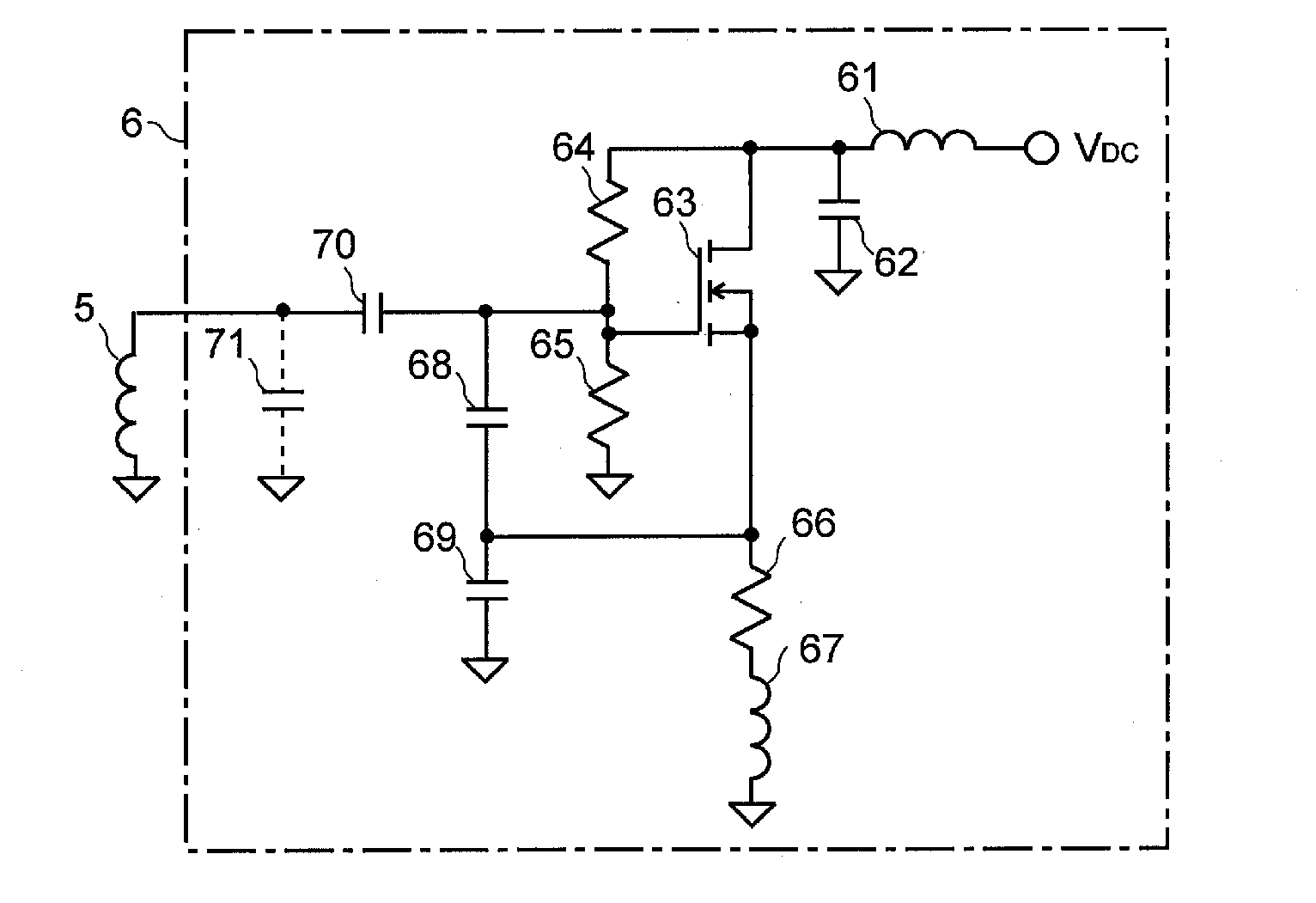
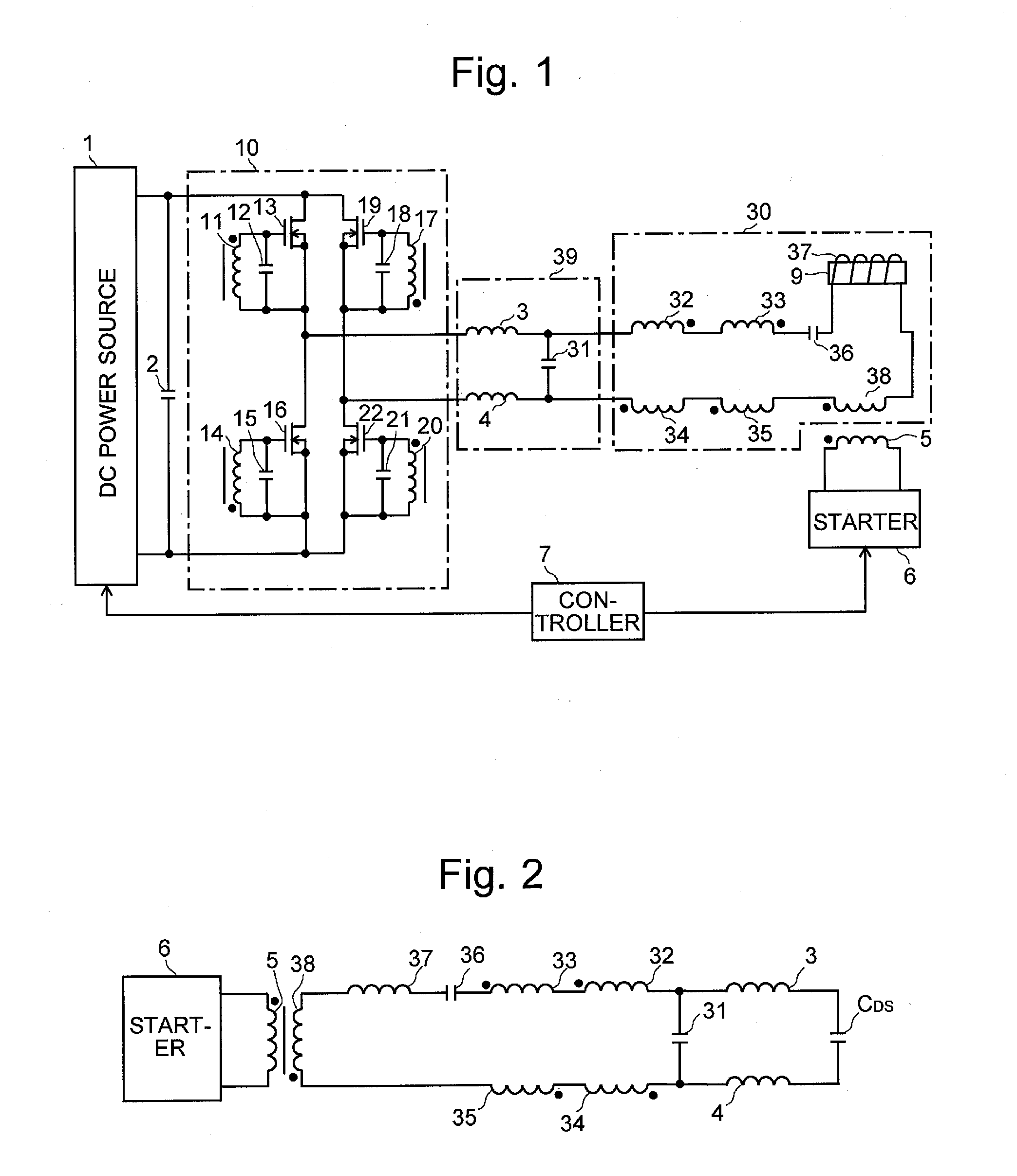
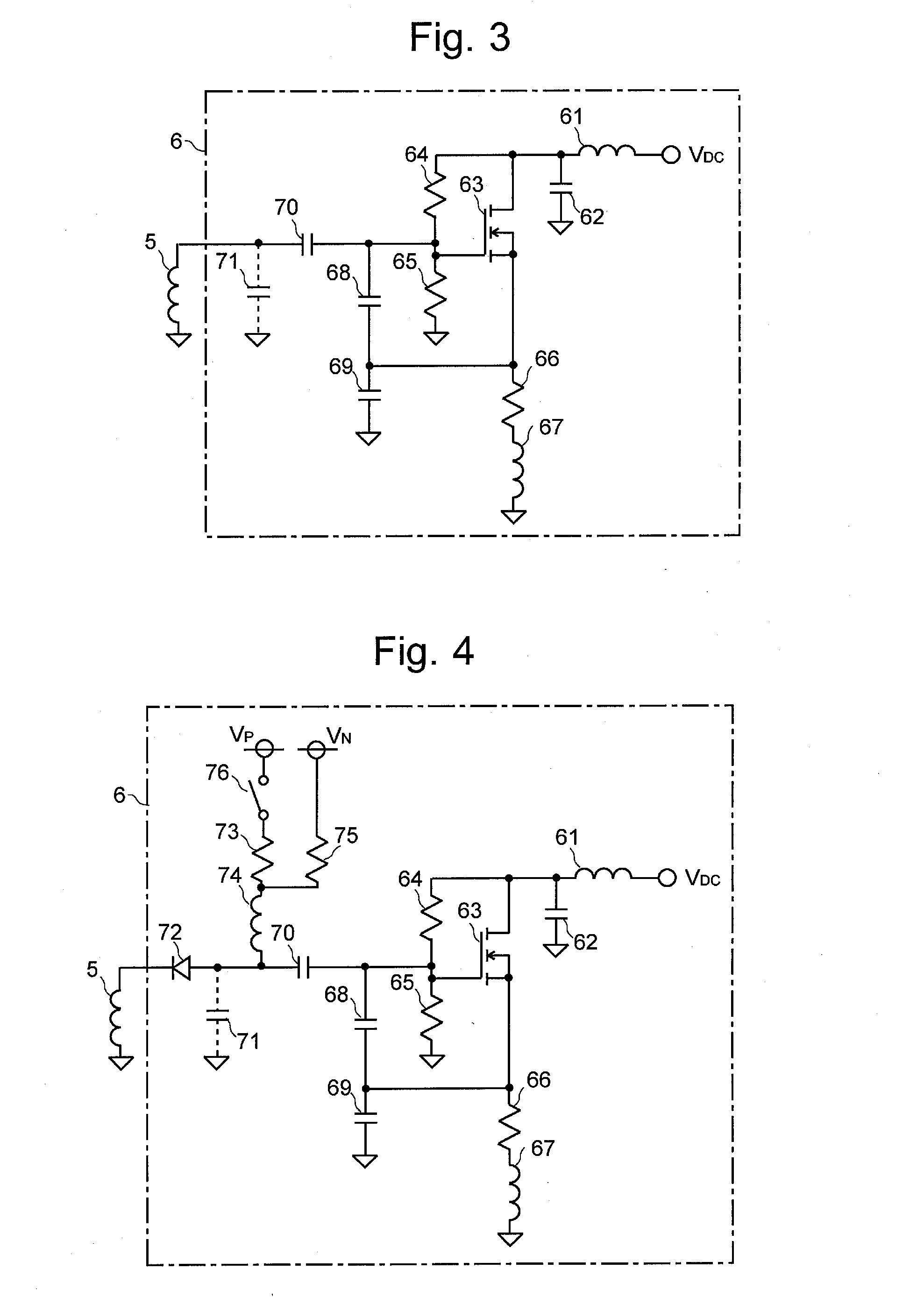
[0029]FIG. 1 is a configuration diagram of the radio-frequency oscillation circuit of the present embodiment, FIG. 2 is a diagram showing an equivalent circuit of the radio-frequency oscillation circuit of the present embodiment, and FIG. 3 is a diagram showing one example of the circuit configuration of the starter in FIG. 1.

[0030]An induction coil 37 wound around a plasma torch 9 of the ICP emission spectrometer to generate plasma in this plasma torch 9 is the target to which a radio-frequency current needs to be supplied in the present radio-frequency oscillation circuit. A capacitor 36 and four primary windings 32, 33, 34 and 35 of a feedback transformer are connected in series with this induction coil 37. Also connected in series with these circuit elements is a seconda...


PUM


Abstract

PROBLEM: To generate a self-oscillation in a stable manner and at a low cost in a self-oscillating radio frequency oscillation circuit for high-power applications used for plasma generation in an ICP emission spectrometer or for other purposes.
SOLUTION: A secondary winding 38 of a starting transformer is arranged in an LC resonance circuit 30 including an induction coil 9, capacitor 36 and other elements. A starter 6, e.g. a Clapp oscillator circuit, is connected to a primary winding 5 magnetically coupled with the winding 38. A radio-frequency current is induced in the LC resonance circuit 30 through the primary and secondary windings 5 and 38 by energizing the starter 6 for a certain period of time in a starting phase. As a result, electric current flows through the secondary windings 11, 14, 17 and 20 in a full-bridge drive circuit 10 which are magnetically coupled with primary windings 32, 33, 34 and 35, respectively, whereby voltage is developed between the gate and source of MOSFETs 13, 16, 19 and 22, causing these MOSFETs 13, 16, 19 and 22 to begin an ON/OFF operation, whereby the self-oscillation is started.

Description

TECHNICAL FIELD[0001]The present invention relates to a radio-frequency oscillation circuit, and more specifically, to a method for starting a radio-frequency oscillation for high-power applications. The radio-frequency oscillation circuit according to the present invention is suitable as a radio-frequency power source for generating and maintaining plasma in an analyzing system or a manufacturing and processing system using plasma, such as an inductively coupled plasma (ICP) emission spectrometer or a plasma chemical vapor deposition (CVD) system.BACKGROUND ART[0002]In an inductively coupled plasma (ICP) emission spectrometer, a plasma-generating gas (e.g. argon) is ionized by an electromagnetic field created by supplying radio-frequency power to an induction coil. While the obtained plasma is maintained by the electromagnetic field, a sample atom is introduced into the plasma. The sample atom is excited by the plasma, and when the excited atom returns to a lower energy level, it e...

Claims


Application Information

Patent Timeline
Patent Type & Authority Applications(United States)
IPC IPC(8): H03B5/06H05H1/24H03B5/12
CPCH03B5/06H05H1/24H03B5/1203H03B5/1228H03B5/1218H05H1/30H05H1/36H05H2242/22H03L3/00H05H1/46H03B5/1296H03B2200/0094H05H1/4652
Inventor HABU, TOSHIYA
Owner SHIMADZU CORP
Why Eureka
Try Eureka