Image display device, image display method, and recording medium

a technology of image display and display method, which is applied in the direction of static indicating devices, instruments, television systems, etc., can solve the problems of inability of nearby people to grasp the status of wearers, inability to know the status of users, and inability to know what users are doing and viewing

a technology of image display and display method, which is applied in the direction of static indicating devices, instruments, television systems, etc., can solve the problems of inability of nearby people to grasp the status of wearers, inability to know the status of users, and inability to know what users are doing and viewing

US20150253573A1Active Publication Date: 2015-09-10SONY CORP

Image

  • Image display device, image display method, and recording medium
  • Image display device, image display method, and recording medium
  • Image display device, image display method, and recording medium

Examples


Embodiment Construction

[0068]Hereinafter, an embodiment of the technology disclosed in this specification will be described in detail and with reference to the drawings.

[0069]As discussed earlier, head-mounted image display devices may be categorized into an opaque type (for example, see Patent Literature 1), and a see-through type (for example, see Patent Literature 2). The technology disclosed in this specification may be applied to either of these types.

[0070]A. Device Configuration

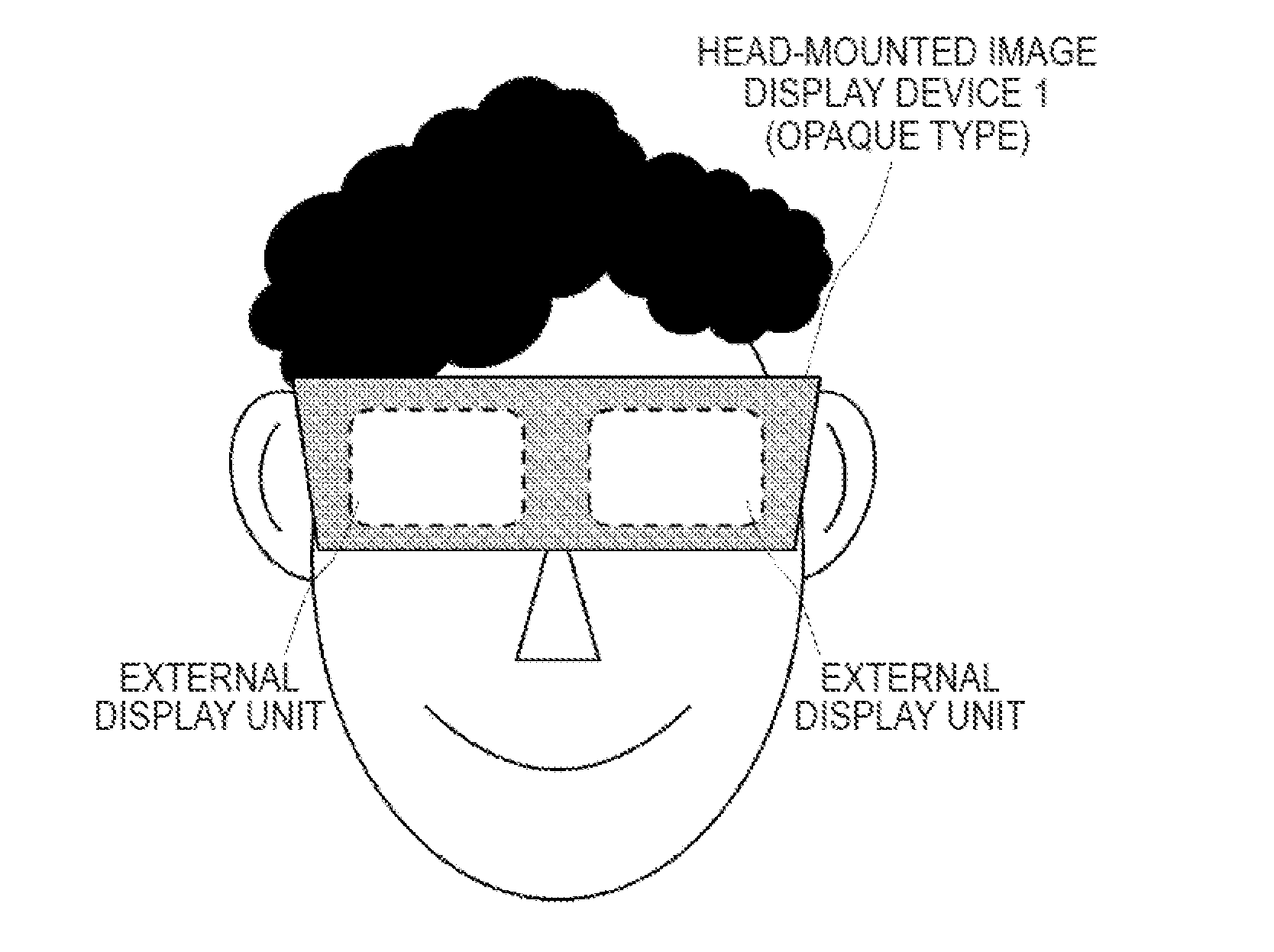
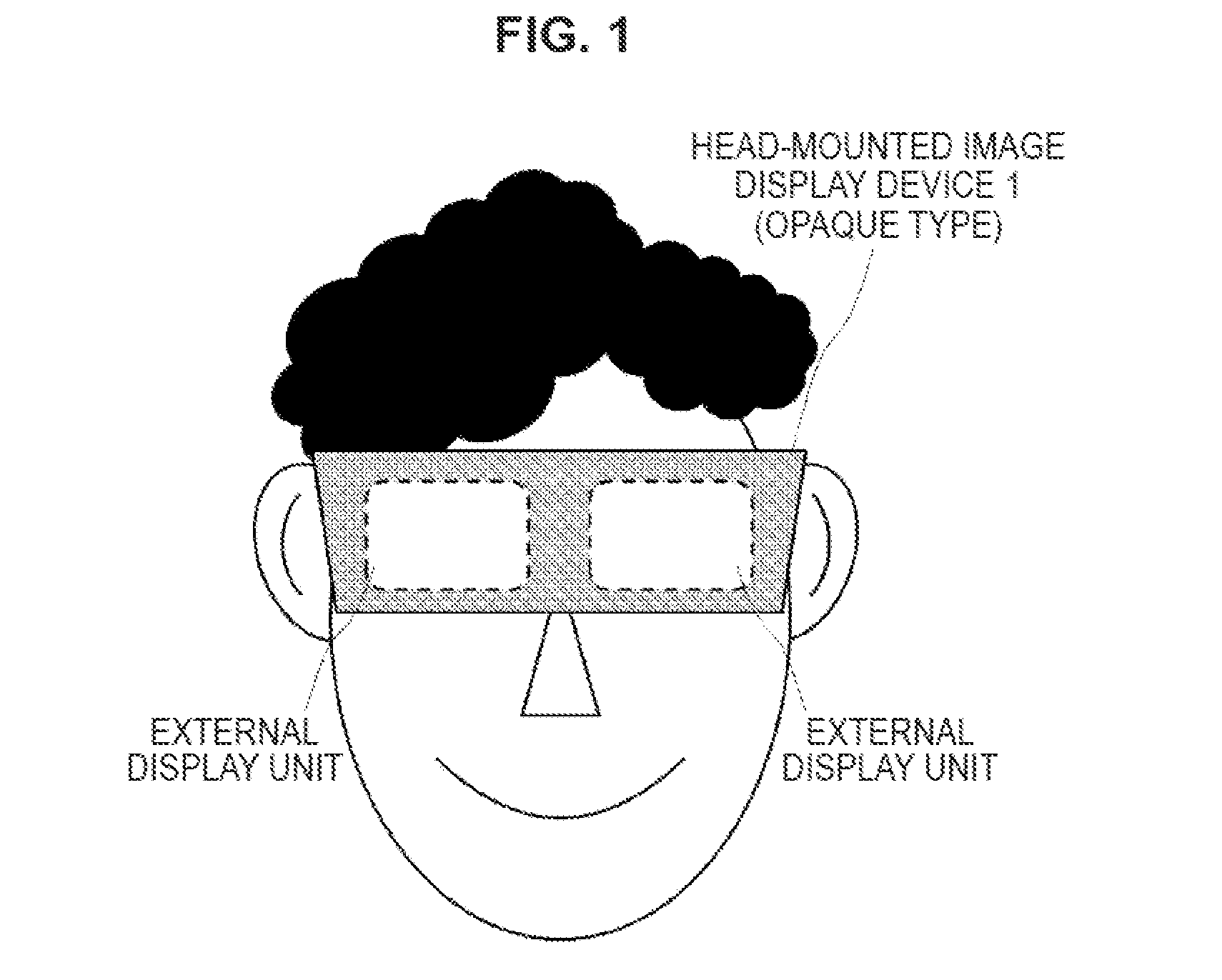
[0071]FIG. 1 illustrates the frontal appearance of a user wearing a head-mounted image display device 1 of the opaque type.

[0072]As illustrated in FIG. 1, the user wears a non-transparent head-mounted image display device 1, and the left and right eyes are covered directly. The side of the head-mounted image display device 1 housing that faces the user's face is defined as “internal”, while the opposite side is defined “external”. While the user wears the head-mounted image display device 1, the internal face is viewable by ...


PUM


Abstract

Provided is an image display device used by being mounted to a head or a face of a user, including a first display unit that displays an internal image seen from a side of the user, a second display unit that displays an external image seen from outside the image display device, and a control unit that controls display of the internal image and the external image.

Description

TECHNICAL FIELD[0001]The technology disclosed in this specification relates to an image display device worn on the head and used to view an image, as well as an image display method and a recording medium, and more particularly, relates to an image display device, an image display method, and a recording medium that enables a viewer to view a display image as an enlarged virtual image with a virtual image optical system.BACKGROUND ART[0002]Head-mounted image display devices that are worn on the head and used to view images, or in other words, head-mounted displays, are known. A head-mounted image display device has an image display unit for each of the left and right eyes, in general, and by combining these with headphones, the head-mounted image display device is configured to enable control of visual perception and auditory perception. In addition, a head-mounted image display device is also capable of showing different images to the left and right eyes, and if an image with paral...

Claims


Application Information

Patent Timeline
10 Sep 2015
Publication
US20150253573A1
IPC
G02B27/01; G09G5/10; G06F3/01
CPC
G02B27/0172; G06F3/013; G09G2360/144; G06F3/015; G06F3/012; G09G5/10; G02B2027/0112; G02B2027/0118
Inventors
SAKO, YOICHIRO; MIYAJIMA, YASUSHI