
Eureka
For R&D, Eureka makes reading and utilizing patents & technical documents easy.
Eureka AIR
Designed for self-driven R&D workflows. Generate viable solutions, solve complex R&D challenges, empower your innovation with AI.

Eureka Materials
Designed for material experts only. Revolutionize your material R&D, from search, analyze, to developing new materials.

TechResearch
Generate reliable direction feasibility study reports for your R&D in just a few steps.

TechSeek
Discover and master advanced knowledge NOW. Basics, ideas, possibilities, all at once.

TechMind
As an expert in R&D Theories, TechMind can generates customized viable solutions instantly.

TechRisk
Analyze your overall solution with one click, know your potential R&D risks in advance.

TechMonitor
Get weekly tech updates, stay abreast of the latest tech innovations and key insights.
Check valve disc position indicator
- Summary
- Abstract
- Description
- Claims
- Application Information
AI Technical Summary
Benefits of technology
Problems solved by technology
Method used
Image

Examples
Embodiment Construction
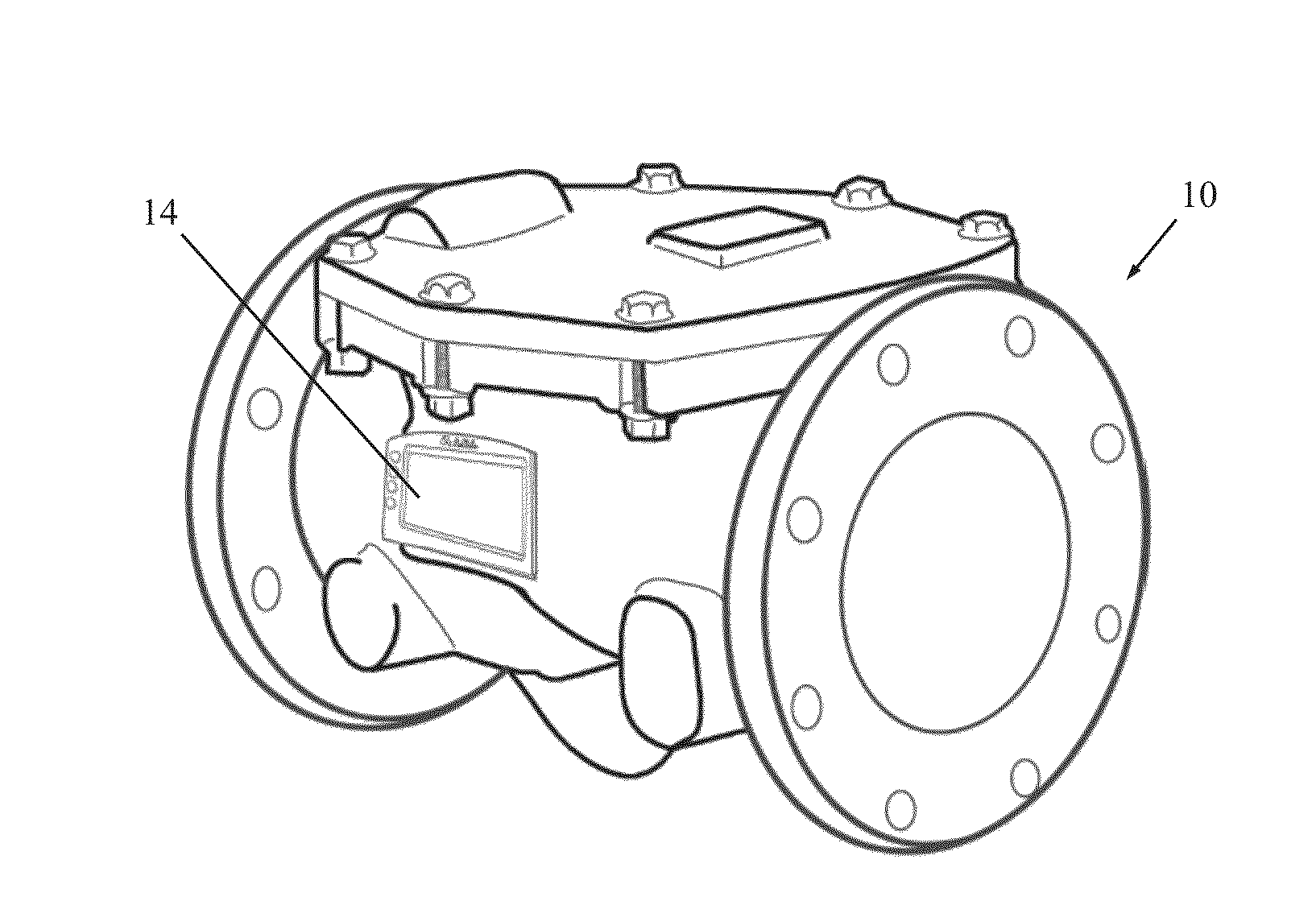
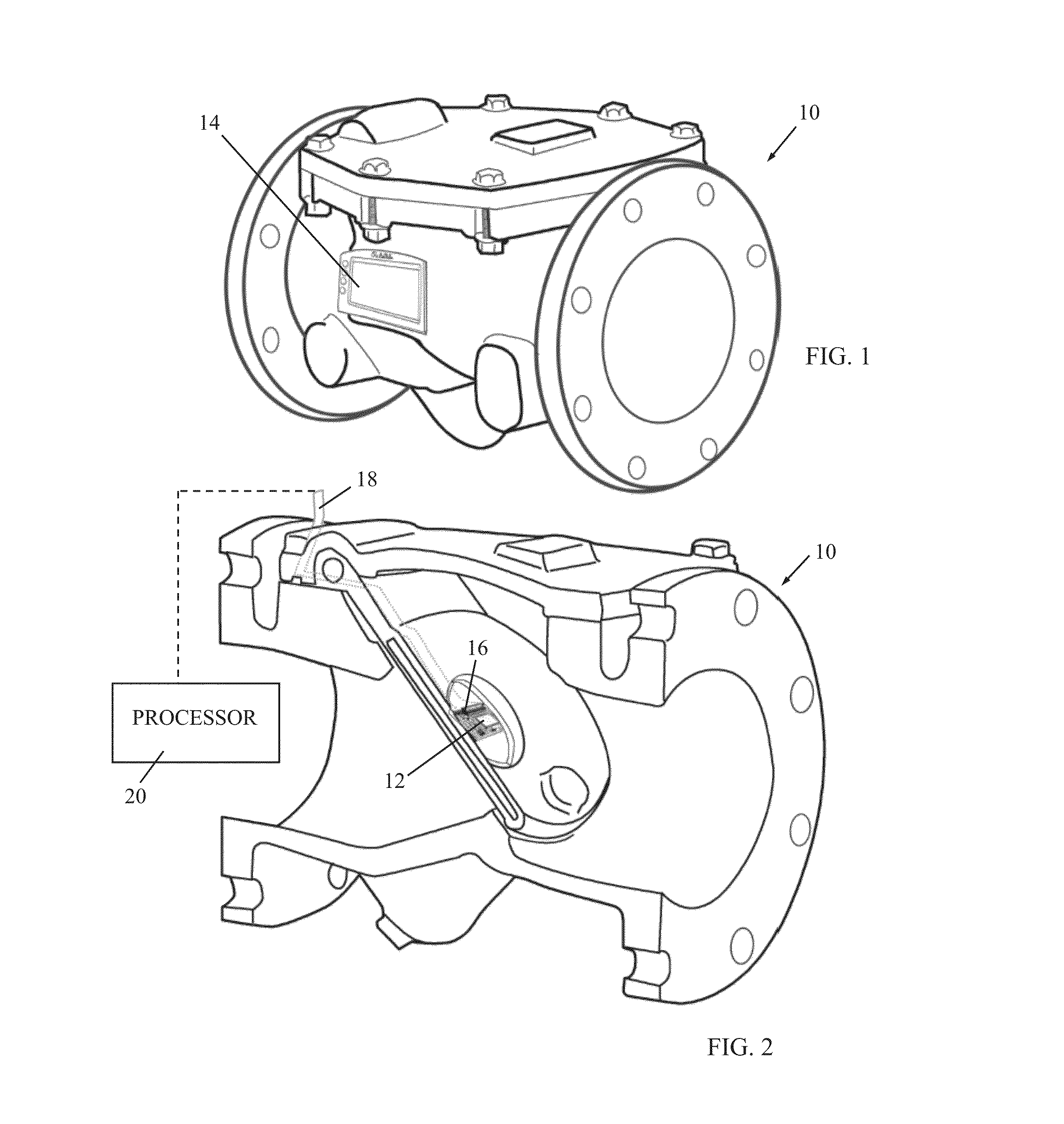
[0012]Reference is now made to FIGS. 1 and 2, which illustrate a check valve 10 with a sensor 12 (FIG. 2) and display 14 (FIG. 1) for showing angular positions of a check valve disc 16 (FIG. 2), constructed and operative in accordance with an embodiment of the present invention.
[0013]In one embodiment, sensor 12 is a miniature accelerometer or other type of electronic inertia / gravity sensor, such as but not limited to a MEMS component, mounted on the check valve disc 16. Sensor 12 may be in wired communication, by means of a data transfer cable 18, with a processor 20, which may be mounted in check valve 10 or may be remote to check valve 10, such as by wireless communication (e.g., BLUETOOTH, WiFi, GSM\GPRS) or by wired communication. Alternatively, sensor 12 can be in wireless communication of any kind with processor 20. Processor 20 outputs the sensed data to display 14, and may be part of a logic analyzing and presentation unit. The drawings show just one possible installation p...
PUM
 Abstract
Description
Claims
Application Information
 - R&D Engineer
- R&D Manager
- IP Professional
- Industry Leading Data Capabilities
- Powerful AI technology
- Patent DNA Extraction
Browse by: Latest US Patents, China's latest patents, Technical Efficacy Thesaurus, Application Domain, Technology Topic, Popular Technical Reports.
© 2024 PatSnap. All rights reserved.Legal|Privacy policy|Modern Slavery Act Transparency Statement|Sitemap|About US| Contact US: help@patsnap.com