Supercharge Your Innovation With Domain-Expert AI Agents!

Laser beam directing system and method for orienting optical components of the laser beam directing system

a laser beam and optical component technology, applied in the direction of optics, mountings, instruments, etc., can solve the problem of inability to adjust the beam path during operations, and achieve the effect of facilitating a highly precise orientation of the laser beam and facilitating a permanent readjustment of the orientation

Active Publication Date: 2015-10-29
MBDA DEUTSCHLAND GMBH
View PDF2 Cites 2 Cited by
  • Summary
  • Abstract
  • Description
  • Claims
  • Application Information

AI Technical Summary

Benefits of technology

The invention provides a laser beam directing system with two auxiliary lasers that are fixed and oriented parallel to the rotation axes of the system. The auxiliary lasers are deflected by optical components of the system and their impact on a detector is compared. This allows the system to adjust its components to ensure that the two auxiliary beams align with each other at the detector. The laser beam directing system can then perform a differential measurement to determine a deviation from orthogonality of the beam path and adjust its components accordingly. The system can also include a first aperture and a second detector to evaluate the alignment of the deflection mirrors of the system. Overall, this invention provides a more precise and accurate orientation of the laser beam.

Problems solved by technology

Furthermore an adjustment of the beam path during operations is not possible.

Method used


Image

  • Laser beam directing system and method for orienting optical components of the laser beam directing system
  • Laser beam directing system and method for orienting optical components of the laser beam directing system
  • Laser beam directing system and method for orienting optical components of the laser beam directing system

Examples


Embodiment Construction

[0050]All figures are mere representations of devices according to the invention or their components according to embodiments of the invention. In particular distances and size relationships in the figures are not represented according to scale. In different figures equivalent elements are provided with identical reference numerals.

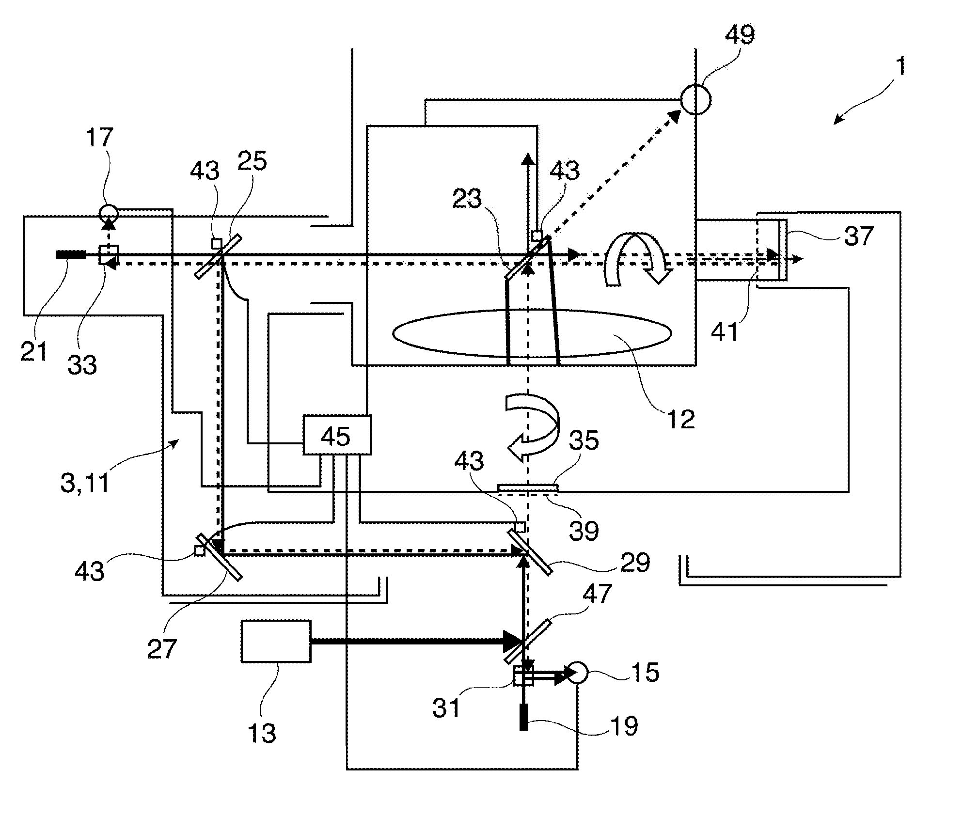
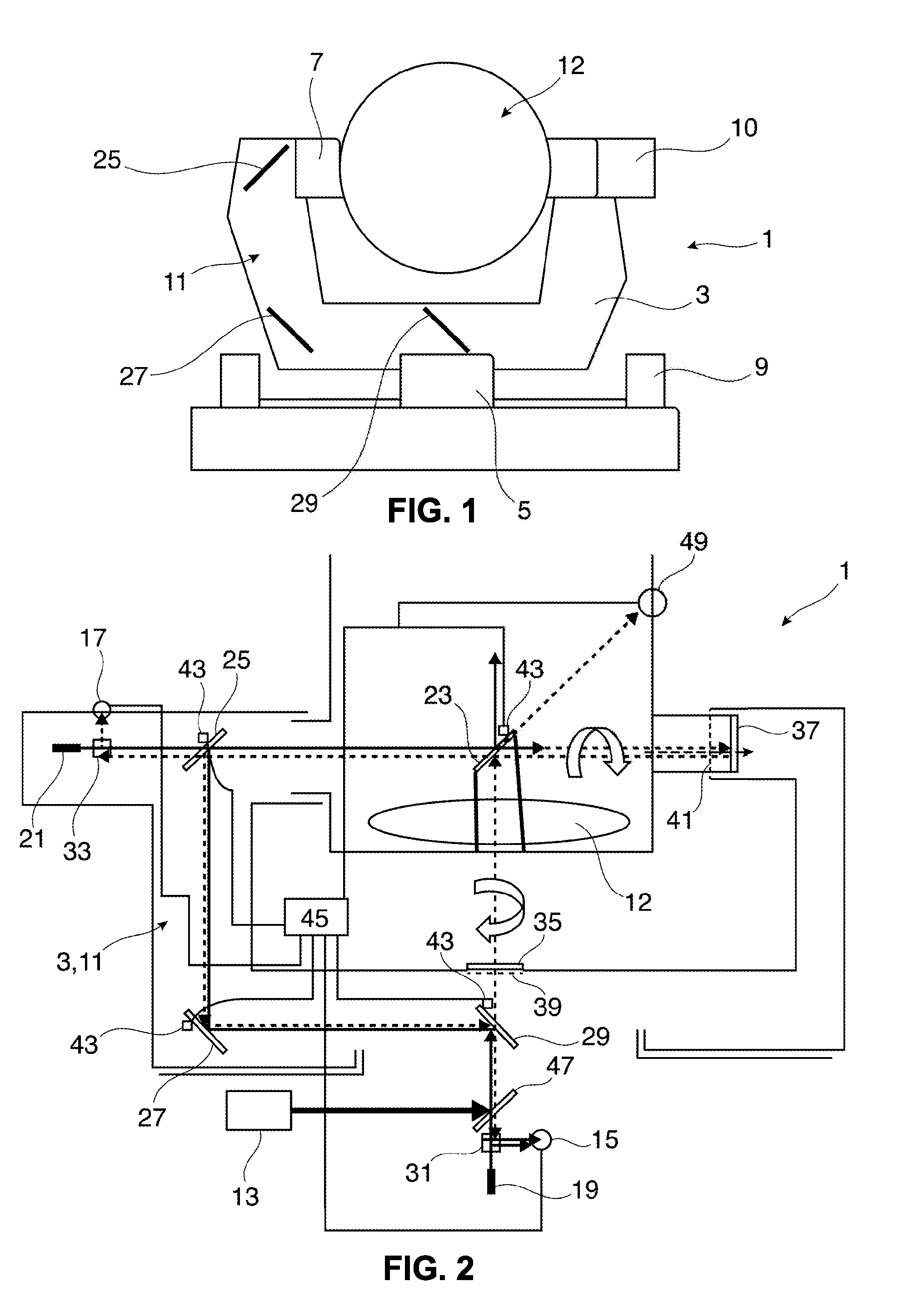
[0051]FIG. 1 illustrates a laser beam directing system for quickly directing a primary laser beam at a target which can move in an entire hemisphere. The primary laser beam is introduced by mirrors that are not visible in FIG. 1 into the Coude optical channel. In the Coude optical channel 11 the primary laser beam is routed by a fourth deflection mirror 29, a third deflection mirror 27 and a second deflection mirror 25 to telescope optics 12. The primary laser beam is coupled into the telescope optics 12 by a first deflection mirror 23 which is not visible in FIG. 1. In the telescope optics 12, the primary laser beam is expanded and focused.

[0052]Using th...


PUM


Abstract

A laser beam directing system including a first deflection mirror which is connected with an elevation axis of the laser beam directing system; a primary laser which is coupleable into telescope optics by the first deflection mirror; a first auxiliary laser that is oriented in parallel to an azimuth rotation axis of the laser beam directing system; a second auxiliary laser that is oriented parallel to an elevation rotation axis of the laser beam directing system; and a first detector, wherein the first auxiliary laser, the second auxiliary laser and the first detector are arranged and oriented in the laser beam directing system so that the first deflection mirror is alignable by comparing beams of the first auxiliary laser and the second auxiliary laser impacting the first detector so that a beam from the primary laser is coupleable into the telescope optics parallel to the elevation rotation axis.

Description

RELATED APPLICATIONS[0001]This application is a continuation of International patent application PCT / DE2013 / 000578 filed on Oct. 9, 2013 claiming priority from German patent application DE 10 2012 019 940.6 filed on Oct. 11, 2012, both of which are incorporated in their entirety by this reference.FIELD OF THE INVENTION[0002]The instant invention relates to a laser beam directing system and to a method for orienting optical components of the laser beam directing system.BACKGROUND OF THE INVENTION[0003]Telescope optics can be used in order to quickly direct a laser beam at a target which can move in an entire hemisphere. The telescope optics can expand a beam coming from the laser and can also focus the beam. Furthermore the laser beam can be tracked to the target by a beam directing unit. Beam directing units of this type typically have two axes of rotation that are moved in azimuth and elevation.[0004]The laser beam can thus be directed in the beam directing unit by plural deflectio...

Claims


Application Information

Patent Timeline
Patent Type & Authority Applications(United States)
IPC IPC(8): G02B26/08
CPCG02B26/0816G02B7/1827G02B26/101G01S7/4972
Inventor PROTZ, RUDOLF
Owner MBDA DEUTSCHLAND GMBH
Features
  • R&D
  • Intellectual Property
  • Life Sciences
  • Materials
  • Tech Scout
  • Unparalleled Data Quality
  • Higher Quality Content
  • 60% Fewer Hallucinations
Learn More