Floor scrubbing machine

Inactive Publication Date: 2015-11-05
FIMAP
View PDF14 Cites 5 Cited by
  • Summary
  • Abstract
  • Description
  • Claims
  • Application Information

AI Technical Summary

Benefits of technology

[0007]The aim of the present disclosure is to provide a floor scrubbing machine that has a very small space

Problems solved by technology

In current machines, the tank for the washing liquid and the tank for collecting the dirty liquid are arranged laterally with respect to a vertical central plane of the machine and therefore the machines have a considerable lateral space occupation, which makes them a

Method used


Image

  • Floor scrubbing machine
  • Floor scrubbing machine
  • Floor scrubbing machine

Examples


Example

DETAILED DESCRIPTION OF THE DRAWINGS

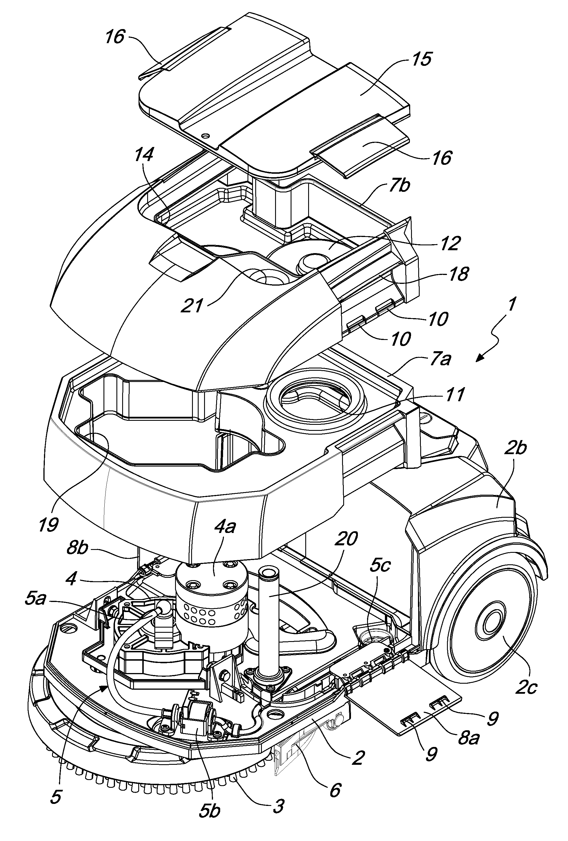
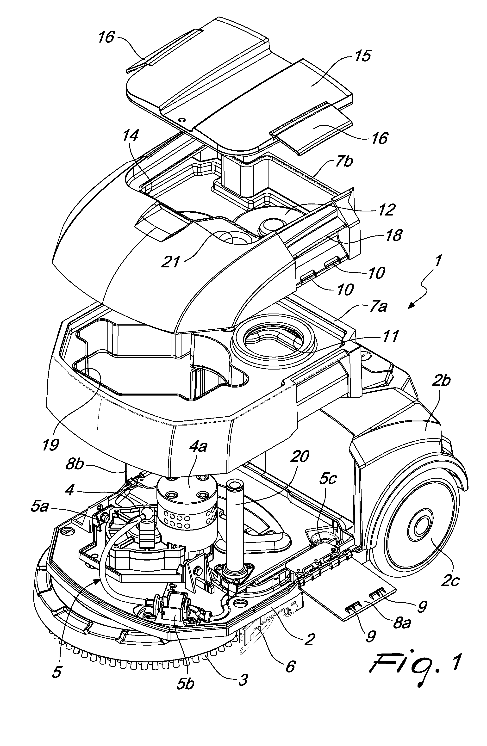
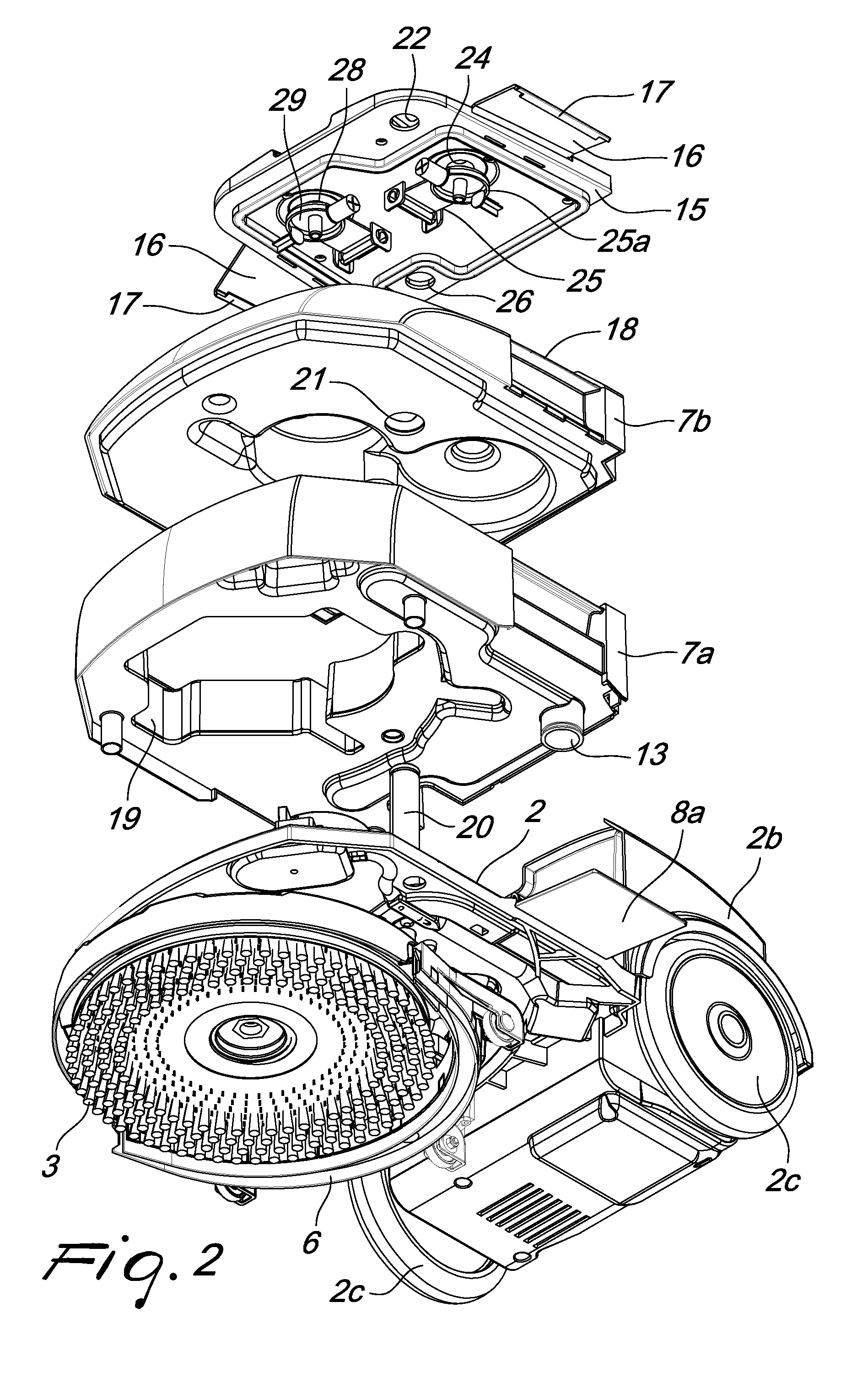
[0018]With reference to the figures, a floor scrubbing machine according to the disclosure, generally designated by the reference numeral 1, comprises a footing 2, which supports at least one brush 3, which can be activated rotationally by an actuation assembly 4, which is also mounted on the footing 2 and comprises an electric motor 4a, and at least one device 5 for dispensing a washing liquid, which is constituted for example by a nozzle 5a and by a pumping device 5b, also mounted on the footing 2 and conveniently connected with its intake to a filter 5c that is also mounted on the footing 2.

[0019]To the rear of the brush 3, the footing 2 further supports a squeegee 6 and at least one suction device, which comprises a suction intake, associated with the squeegee 6, which allows to pick up from the floor the washing liquid and the dirt removed by the brush 3, in order to leave the floor dry and clean when the machine passes.

[0020]An enclosure 2b ...


PUM


Abstract

A floor scrubbing machine includes a footing that supports at least one brush, which can be actuated rotationally by an actuation assembly. The machine further includes at least one device for dispensing a washing liquid, a squeegee arranged to the rear of the brush, and at least one device for aspirating from the floor the washing liquid and the dirt removed by the brush. Additionally, the machine includes a pair of box-like bodies, each of which forms a respective tank for containing a liquid processed by the machine. The box-like bodies are stacked on each other on the footing. Removable retention elements are provided which act between the footing and the box-like body that lies above the other box-like body in order to retain the box-like bodies against each other and against the footing.

Description

FIELD[0001]The present disclosure relates to a floor scrubbing machine.BACKGROUND[0002]Conventional floor scrubbing machines have a supporting base for at least one rotating brush and for at least one dispenser of a washing liquid.[0003]To the rear of the brush, along the forward direction of travel of the machine, there is a squeegee that retains the washing liquid and the dirt removed from the floor so that they are picked up by an intake so as to leave the floor dry and clean.[0004]A tank for the washing liquid, which supplies the dispenser, and a tank for collecting the dirty liquid drawn by the intake are mounted on the supporting base.[0005]In current machines, the tank for the washing liquid and the tank for collecting the dirty liquid are arranged laterally with respect to a vertical central plane of the machine and therefore the machines have a considerable lateral space occupation, which makes them awkward to use in tight spaces, such as for example in a home environment.[...

Claims


Application Information

Patent Timeline
IPC IPC(8): A47L11/03A47L11/30A47L11/40A47L11/283
CPCA47L11/03A47L11/283A47L11/4083A47L11/4016A47L11/305
Inventor RUFFO, MASSIMILIANO
Owner FIMAP
Why Eureka
Try Eureka