Bench vise with dual axis position adjustment and control

A technology of bench vise and bearing group, applied in the field of bench vise, can solve the problem of high operation difficulty, achieve the effect of ensuring the position accuracy, preventing the deviation of the set position, and reducing the overall volume

Active Publication Date: 2020-07-17
SHANGHAI INST OF TECH
View PDF12 Cites 0 Cited by
  • Summary
  • Abstract
  • Description
  • Claims
  • Application Information

AI Technical Summary

Problems solved by technology

For such a simple process, three times of clamping must be completed on an ordinary bench vise to process, which has strict requirements on the clamping process and clamping surface, and the operation is extremely difficult

Method used


Image

  • Bench vise with dual axis position adjustment and control
  • Bench vise with dual axis position adjustment and control
  • Bench vise with dual axis position adjustment and control

Examples


Embodiment

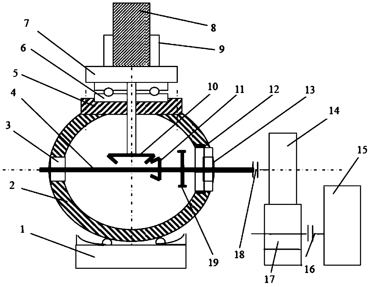
[0054] Such as image 3 , shown in 4, a multi-degree-of-freedom bench vise for adjusting position and direction, including a machine base 1, a spherical shell 2, a bearing group a3, a main drive shaft 4, a cover 5, a plane bearing 6, a fixture base 7, and a workpiece 8. Fixture assembly 9, large bevel gear 10, small bevel gear 11, inner ring gear 12, bearing group b 13, drive motor assembly 14, feed system 15, coupling one 16, lead screw and nut assembly 17, coupling Shaft device two 18, spur gear 19.

[0055] A spherical shell 2 is installed on the base 1, and the arc groove on the top of the base 1 matches the spherical shell 2, and balls are arranged at the joint between the arc groove on the top of the base 1 and the spherical shell 2. The upper end of the spherical shell 2 is fixedly connected to the cover 5, and the main transmission shaft 4 arranged horizontally is housed inside. The main transmission shaft 4 is equipped with a small bevel gear 11 and a spur gear 19. ...


PUM


Abstract

The invention relates to a bench vise with the biaxial position capable of being adjusted and controlled. An arc-shaped groove on the upper portion of a machine base matches a spherical shell, and a ball bearing is arranged at the fit connection between the arc-shaped groove on the upper portion of the machine base and the spherical housing; the spherical housing is internally provided with a maintransmission shaft arranged horizontally, and the main transmission shaft is provided with a small bevel gear and a spur gear; the front and rear ends of the main transmission shaft are both connected with the spherical housing through two bearing groups, and the main transmission shaft can slide in the axial direction of the bearing groups; the spur gear on the main transmission shaft is matchedwith an inner gear ring at the interior of the right end of the spherical housing; a sealing cover on the upper portion of the spherical housing is connected with a fixture base through a plane bearing, and a fixture assembly is mounted on the fixture base; the bottom of the fixture base is connected with a large bevel gear through a vertical rotating shaft, and the large bevel gear is matched with the small bevel gear on the main transmission shaft; and the main transmission shaft is connected with a driving motor assembly through a second coupling, a lead screw and a nut assembly are installed on the lower portion of the driving motor assembly, and the lead screw and the nut assembly are connected with a feeding system through a first coupling.

Description

technical field [0001] The invention relates to a bench vise, in particular to a bench vise capable of adjusting position and direction with multiple degrees of freedom. Background technique [0002] The main function of the ordinary bench vise is to clamp the workpiece. During the processing of the parts, it mainly completes the role of fixing and clamping the workpiece. During the processing of polyhedral parts, since several surfaces are required to be processed, the traditional vise needs to constantly change the clamping surface to complete the work. This will bring inconvenience to some processing indication requirements on each processing surface, especially for some processing indications that require strict interrelationships. Take a simple part processing requirement as an example; such as figure 1 as shown, figure 1 It is required that the first through hole 31 is perpendicular to the second through hole 32, and the counterbore 33 is perpendicular to the first ...

Claims


Application Information

Patent Timeline
Patent Type & Authority Patents(China)
IPC IPC(8): B25B1/22
CPCB25B1/22
Inventor 纪林章沈忠石钢周帅
Owner SHANGHAI INST OF TECH
Why Eureka
Try Eureka