Near-infrared aircraft attitude and position measurement objective lens system

An aircraft and near-infrared technology, applied in instruments, optics, integrated navigators, etc., can solve the problems of large optical system aperture, difficult processing and detection, and unknown space adaptability, so as to reduce the difficulty of detection and improve the uniformity of imaging illumination , The effect of high reliability in space work

Active Publication Date: 2015-08-19
CHANGCHUN INST OF OPTICS FINE MECHANICS & PHYSICS CHINESE ACAD OF SCI
View PDF3 Cites 0 Cited by
  • Summary
  • Abstract
  • Description
  • Claims
  • Application Information

AI Technical Summary

Problems solved by technology

However, the system contains a parabolic reflective surface, a hyperboloid reflective surface, a high-order aspheric surface, and a concave ellipsoidal surface, which are difficult to process and detect. At the same time, the large diameter of the optical system results in a large volume and a small viewing angle. The observation field is too small when the object distance is not large
[0010] When the finite object distance of the imaging device in the above-mentioned patent changes, the position of the center of mass of the imaging energy of the incident light of a certain field of view will change, and the complex structure will occupy a large space volume, and the space adaptability is unknown. The launch cost brought by its own weight will also increase accordingly

Method used


Image

  • Near-infrared aircraft attitude and position measurement objective lens system
  • Near-infrared aircraft attitude and position measurement objective lens system
  • Near-infrared aircraft attitude and position measurement objective lens system

Examples


specific Embodiment 1

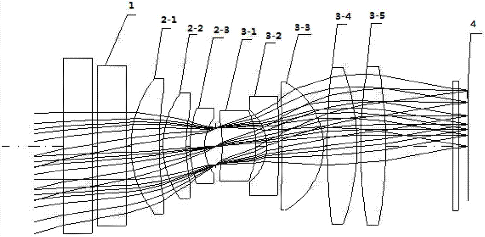
[0039] The air interval between the flat filter 1 and the flat glass on its left side is 0.5mm; the air interval between the first positive meniscus lens 2-1 and the second positive meniscus lens 2-2 in the front lens group 2 is 0.4mm, and the second The air interval between the positive meniscus lens 2-2 and the third negative meniscus lens 2-3 is 0.4mm; the air space between the first positive meniscus lens 3-1 and the second negative meniscus lens 3-2 in the rear mirror group The interval is 1.13mm, the air interval between the second negative meniscus lens 3-2 and the third positive meniscus lens 3-3 is 0.4mm, the air interval between the third positive meniscus lens 3-3 and the first biconvex lens 3-4 The interval is 0.4mm, the air interval between the first lenticular lens 3-4 and the second lenticular lens 3-5 is 0.39mm; the air interval between the flat filter 1 and the first positive meniscus lens 2-1 of the front lens group 2 is 0.5mm mm, the air gap between the thir...


PUM


Abstract

An objective lens system for near-infrared flight vehicle attitude and position measurement belongs to the field of optical system design. The objective lens system comprises a flat filtering piece, a front lens group, a rear lens group and a CCD (Charge Coupled Device) which are coaxially arranged from the left to the right. The front lens group comprises a first positive meniscus lens, a second positive meniscus lens and a third positive meniscus lens which are sequentially arranged from the left to the right and are spherical mirror lenses. The rear lens group comprises a first negative meniscus lens, a second negative meniscus lens, a third negative meniscus lens, a first biconvex lens and a second biconvex lens which are sequentially arranged from the left to the right and are spherical mirror lenses. The light passes through the flat filtering piece, the front lens group and the rear lens group and is imaged on the CCD. The objective lens system is applicable to the band of 0. 79 to 0.88mu m, the range of the full field of view 2 omega >= 32 degrees, the focal length f' = 20mm, the relative aperture D / f' = 1 / 2.85, the resolution in the full field of view of 0.5 to 150m, the full band absolute distortion which is less than 1.5mu m, the color deviation which is less than or equal to 0.5mu m and the working temperature ranging from -70 DEG C to +70 DEG C.

Description

technical field [0001] The invention belongs to the field of optical design, and relates to an objective lens system, in particular to an objective lens system for measuring the attitude and position of a near-infrared aircraft. Background technique [0002] To achieve in-orbit docking of two vehicles flying in orbit, a special docking mechanism is required. [0003] In the existing photoelectric equipment, the position and attitude measurement of the target aircraft usually uses star sensors to image stars, and the attitude and position of the target aircraft can be determined by looking up the ephemeris from the star images. But the star sensor is to image the infinite star, and the focal plane of the infinite star imaging is located on the surface of the CCD, but when the tracking aircraft is constantly approaching the target aircraft, the marker light on the target aircraft is imaged on the star sensor CCD on the tracking aircraft Larger image motion will be generated a...

Claims


Application Information

Patent Timeline
Patent Type & Authority Patents(China)
IPC IPC(8): G02B13/06G02B13/00G02B13/14G01C21/24
Inventor 刘伟奇吕博张大亮姜珊康玉思
Owner CHANGCHUN INST OF OPTICS FINE MECHANICS & PHYSICS CHINESE ACAD OF SCI
Why Eureka
Try Eureka