An air-filled metal planar array antenna

A planar array antenna, metal-filled technology, applied in antennas, antenna arrays, antenna arrays that are energized separately, etc., can solve problems such as difficulty in implementation and wide operating frequency bands, and achieve high integration, wide-band radiation characteristics, and easy processing. Effect

Active Publication Date: 2020-10-09
BEIJING JIAOTONG UNIV
View PDF9 Cites 1 Cited by
  • Summary
  • Abstract
  • Description
  • Claims
  • Application Information

AI Technical Summary

Problems solved by technology

At present, all kinds of air waveguide parallel feeding networks are mostly based on T-shaped structure cascading design, usually using one or more sets of diaphragms to achieve matching, because the electromagnetic energy is reflected multiple times at different branches, it is difficult to achieve a wider working frequency band, so it is necessary to design a new broadband electromagnetic energy distribution structure

Method used


Image

  • An air-filled metal planar array antenna
  • An air-filled metal planar array antenna
  • An air-filled metal planar array antenna

Examples


Embodiment

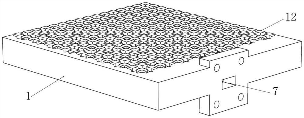
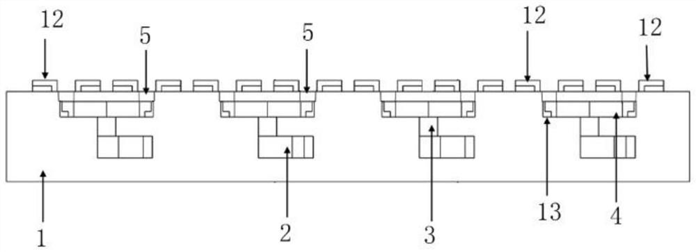
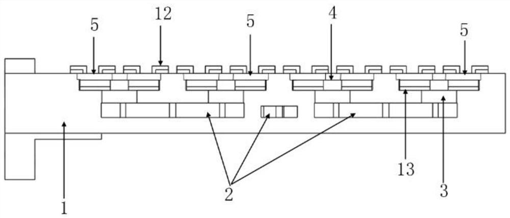
[0048] Such as Figure 1 to Figure 4 As shown, the embodiment of the present invention provides an air-filled metal planar array antenna, including a feed network disposed inside the metal base 1 and a radiation unit located on the upper part of the metal base 1;

[0049] The feeding network includes an air power distribution network 2 , a first air vertical waveguide 3 , an air cavity 4 and a second air vertical waveguide 5 .

[0050] Such as Figure 5 to Figure 8 As shown, the air power distribution network 2 includes a plurality of transmission segments, and the two transmission segments connected to each other are perpendicular to each other to form a T-shaped connection structure, and the electromagnetic energy is distributed in equal amounts in each T-shaped connection structure; wherein,

[0051] One end of a primary transmission segment 6 is a standard waveguide port 7, and the other end of the primary transmission segment 6 is connected to a secondary transmission se...


PUM


Abstract

The invention provides an air filler metal planar array antenna and belongs to the technical field of array antennas. The air filler metal planar array antenna comprises an air power dividing network,wherein two transmission segments connected to each other in the air power dividing network form a T-shaped connection structure; electromagnetic energy is equally distributed in each T-shaped connection structure; the two ends of the last transmission segment are provided with first air vertical waveguides; the upper surface of each first air vertical waveguide is connected to an air cavity; four second air vertical waveguides are arranged centrally symmetrically on the air cavity; four radiating element individuals are centrally symmetrically distributed on the two sides of the long side ofthe two air vertical waveguides. The air filler metal planar array antenna is compact in structure, high in integration degree, small in space volume and easy to machine and realizes radiating elements with wideband radiation characteristics. The radiating elements and a feed network can be well matched, and the electromagnetic energy can be efficiently transmitted and effectively allocated in amultilayer metal cavity so as to ensure that the antenna has a wide frequency band, high gain and stable radiation characteristics.

Description

technical field [0001] The invention relates to the technical field of array antennas, in particular to an air-filled metal planar array antenna with wide frequency band and stable radiation characteristics. Background technique [0002] With the development of electronic science and wireless communication technology, in order to meet the needs of high capacity, high speed, and low delay in mobile communication systems, modern communication antennas need to develop in the direction of broadband, high gain, and miniaturization. Array antennas have good beamforming capabilities, and are easy to achieve high directivity, high gain, and shapeable beams. They are an important technical means to achieve broadband and high gain characteristics. An array antenna usually consists of a feed network and a radiating element. As an important part of the array antenna to realize the effective distribution of electromagnetic energy, the feed network's insertion loss will directly limit th...

Claims


Application Information

Patent Timeline
Patent Type & Authority Patents(China)
IPC IPC(8): H01Q21/00H01Q21/06H01Q1/50H01Q1/36
CPCH01Q1/36H01Q1/50H01Q21/0006H01Q21/061
Inventor 李雨键孙凡淇王均宏
Owner BEIJING JIAOTONG UNIV
Why Eureka
Try Eureka