
Components with multiple energization elements for biomedical devices

a biomedical device and energization element technology, applied in the direction of instruments, spectales/goggles, therapy, etc., can solve the problems of challenging environments for the definition of various functionalities, and achieve the effect of reducing the number of energizing elements

Active Publication Date: 2015-11-12
JOHNSON & JOHNSON VISION CARE INC
View PDF0 Cites 68 Cited by
  • Summary
  • Abstract
  • Description
  • Claims
  • Application Information

AI Technical Summary

Benefits of technology

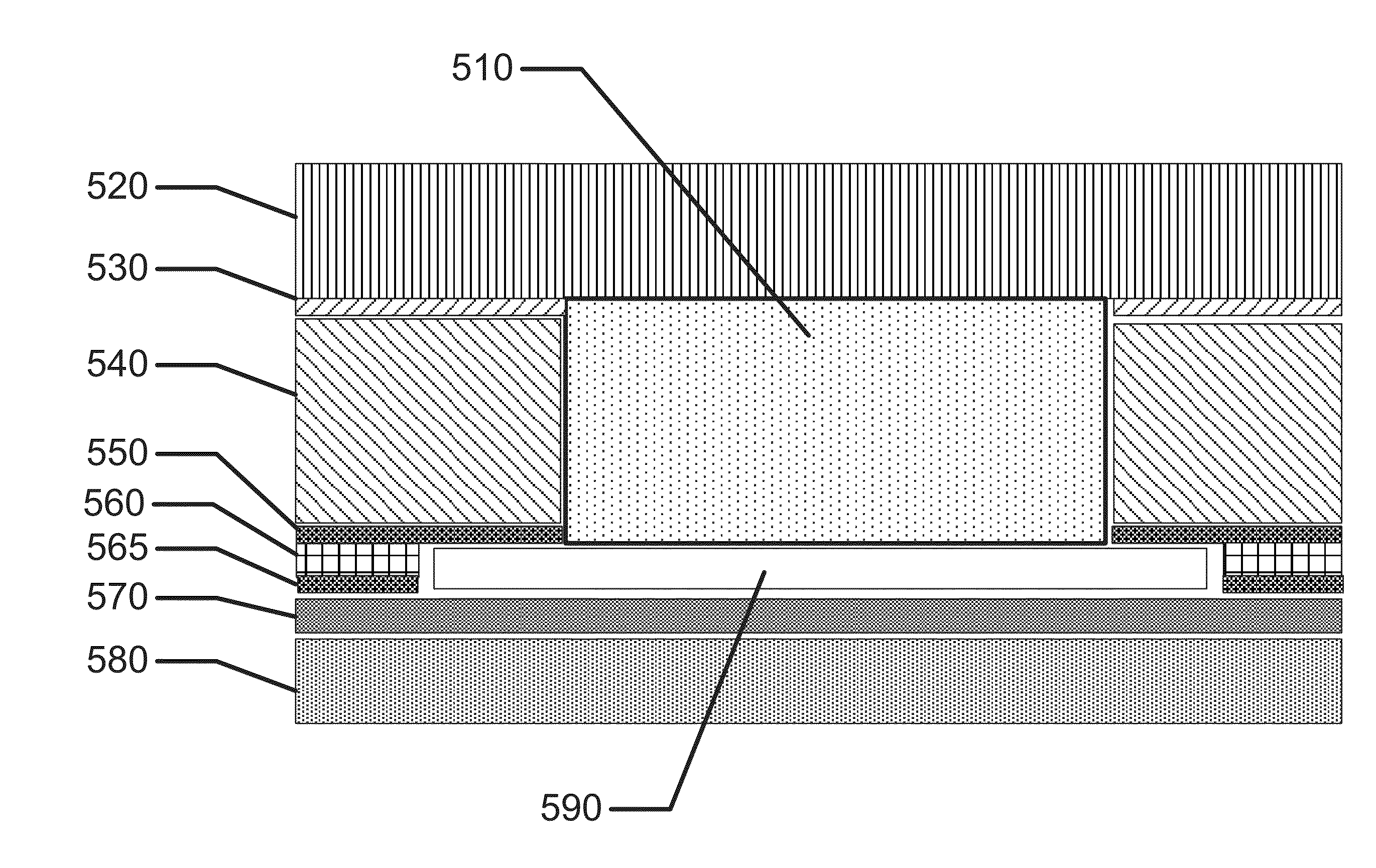
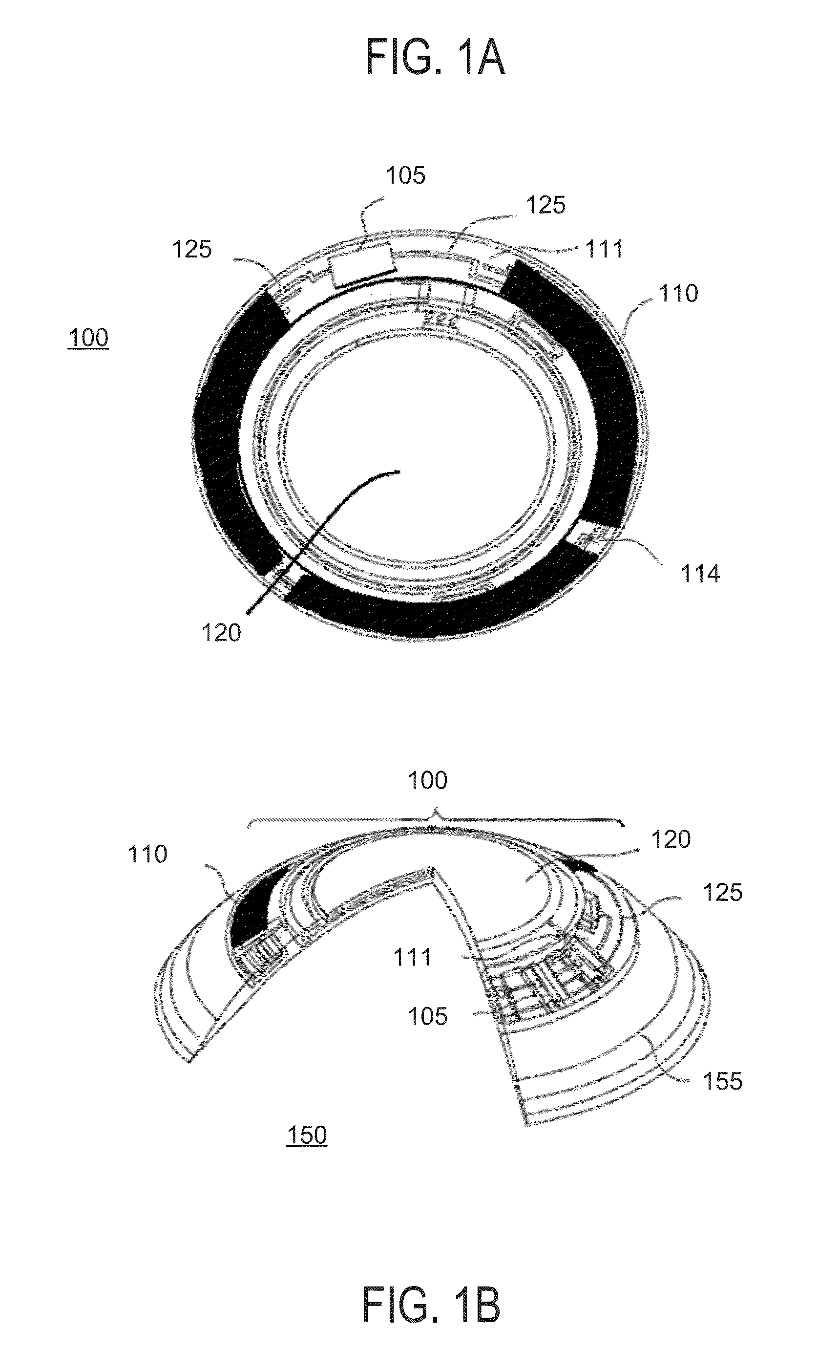
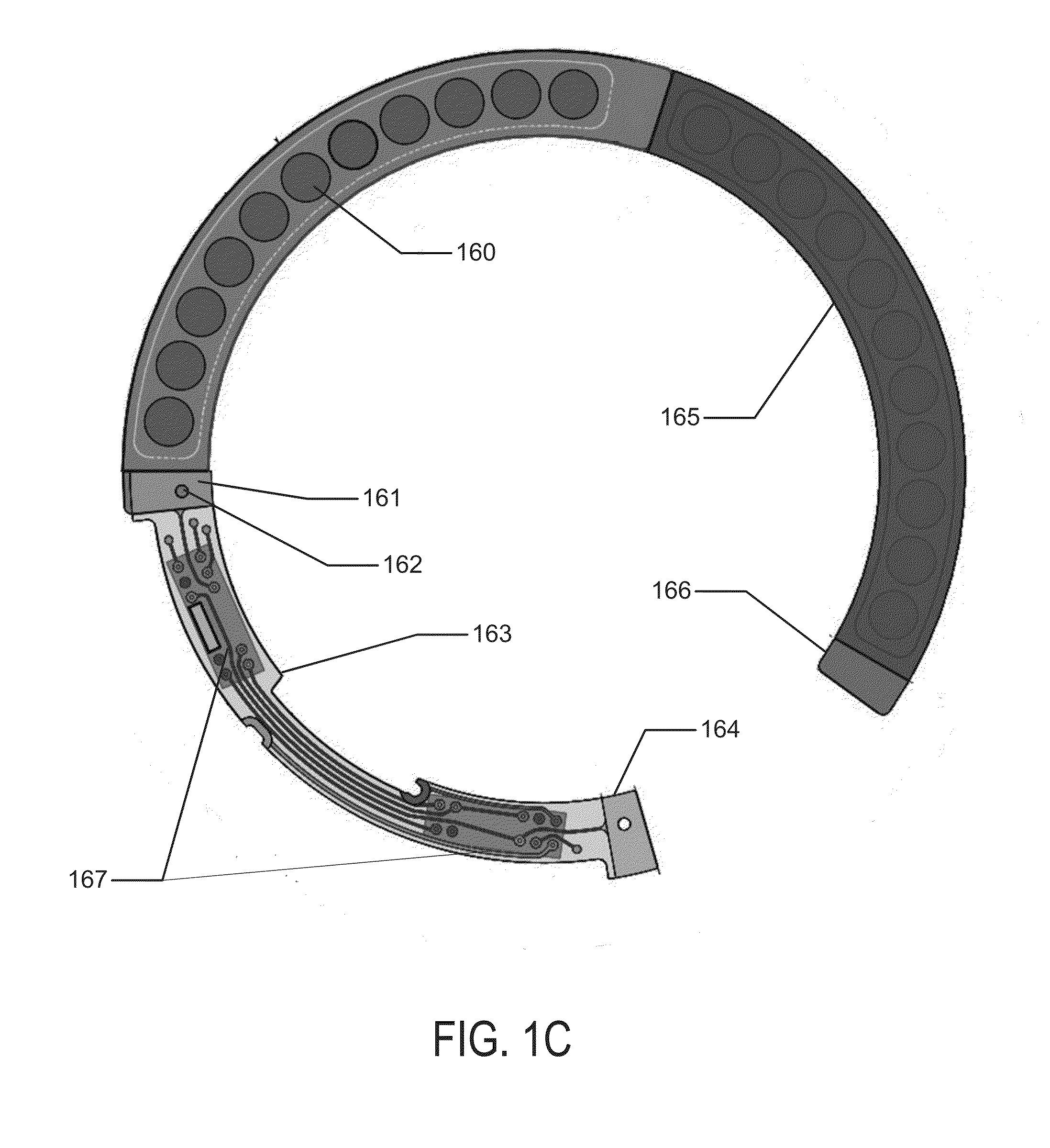
The patent text describes a method and apparatus for creating biocompatible batteries for use in biomedical devices, such as contact lenses. The method involves creating a laminate battery with multiple energization elements, including cathode and anode chemicals, and an electrolyte. The method also involves creating cavities within the battery to hold the chemicals, and attaching current collectors to the battery. The technical effects of this patent include creating a battery with multiple energization elements that can be charged and discharged multiple times, and the ability to control the quantities of each chemical in the battery. The biocompatible battery can also be used in ophthalmic devices, such as contact lenses, and can provide power to components within the device.

Problems solved by technology

However, such semiconductor components require energy and, thus, energization elements should preferably also be included in such biocompatible devices.
The topology and relatively small size of the biocompatible devices creates novel and challenging environments for the definition of various functionalities.

Method used


Image

  • Components with multiple energization elements for biomedical devices
  • Components with multiple energization elements for biomedical devices
  • Components with multiple energization elements for biomedical devices

Examples


Embodiment Construction

[0030]Methods and apparatus to form three-dimensional biocompatible energization elements are disclosed in this application. The separator element within the energization elements may be formed with novel methods and may comprise novel materials. In the following sections, detailed descriptions of various embodiments are described. The description of both preferred and alternative embodiments are exemplary embodiments only, and various modifications and alterations may be apparent to those skilled in the art. Therefore, the exemplary embodiments do not limit the scope of this application. The three-dimensional biocompatible energization elements are designed for use in or proximate to the body of a living organism.

GLOSSARY

[0031]In the description and claims below, various terms may be used for which the following definitions will apply:

[0032]“Anode” as used herein refers to an electrode through which electric current flows into a polarized electrical device. The direction of electri...


PUM

PropertyMeasurementUnit
turn-on voltagesaaaaaaaaaa
feature sizeaaaaaaaaaa
cutoff voltageaaaaaaaaaa

Abstract

Methods and apparatus to form biocompatible energization elements are described. In some embodiments, the methods and apparatus to form the biocompatible energization elements involve forming cavities comprising active cathode chemistry. The active elements of the cathode and anode are sealed with a laminate stack of biocompatible material. In some embodiments, a field of use for the methods and apparatus may include any biocompatible device or product that requires energization elements.

Description

CROSS REFERENCE TO RELATED APPLICATIONS[0001]This application claims the benefit of U.S. Provisional Application No. 62 / 040,178 filed Aug. 21, 2014, and is a continuation-in-part of U.S. application Ser. No. 13 / 358,916, filed Jan. 26, 2012, which claims the benefit of U.S. Provisional Application No. 61 / 454,205, filed Mar. 18, 2011.BACKGROUND OF THE INVENTION[0002]1. Field of the Invention[0003]Methods and apparatus to form biocompatible energization elements are described. In some embodiments, the methods and apparatus to form the biocompatible energization elements involve forming a separator element of the energization element. The active elements including anodes, cathodes and electrolytes may be electrochemically connected and may interact with the formed separator elements. In some embodiments, a field of use for the methods and apparatus may include any biocompatible device or product that requires energization elements.[0004]2. Discussion of the Related Art[0005]Recently, th...

Claims


Application Information

Patent Timeline
Patent Type & Authority Applications(United States)
IPC IPC(8): G02C7/08G02C7/04H01M50/209H01M50/211
CPCG02C7/083G02C2202/16G02C7/04H01L2224/45139H01L2224/48145H01L2924/00014H01L2924/01015H01L2924/01047H01L2924/10253H01L2924/13091A61N1/378Y02E60/10H01M50/209H01M50/211H01L2924/00011H01L2924/00H01L2924/00012H01L2924/01049
Inventor FLITSCH, FREDERICK A.OTTS, DANIEL B.PUGH, RANDALL B.RIALL, JAMES DANIELTONER, ADAM
Owner JOHNSON & JOHNSON VISION CARE INC
Learn More