Screwdriver

Inactive Publication Date: 2015-11-26
HANGZHOU GREAT STAR TOOLS +1
View PDF10 Cites 4 Cited by
  • Summary
  • Abstract
  • Description
  • Claims
  • Application Information

AI Technical Summary

Benefits of technology

[0004]The object of the present invention is to provide a screwdriver with high efficiency for use,

Problems solved by technology

Typically, the handle is manually turned in a full circle, and the shaft rotates in a full circle, until the screw i

Method used


Image

  • Screwdriver
  • Screwdriver
  • Screwdriver

Examples


Example

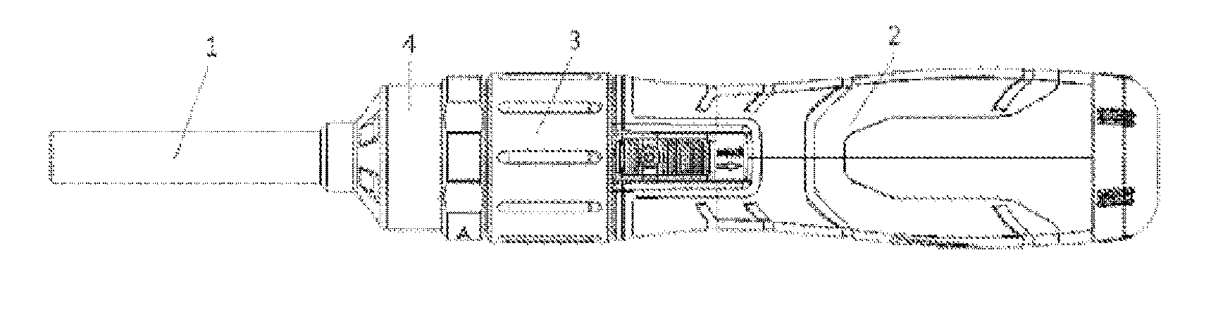
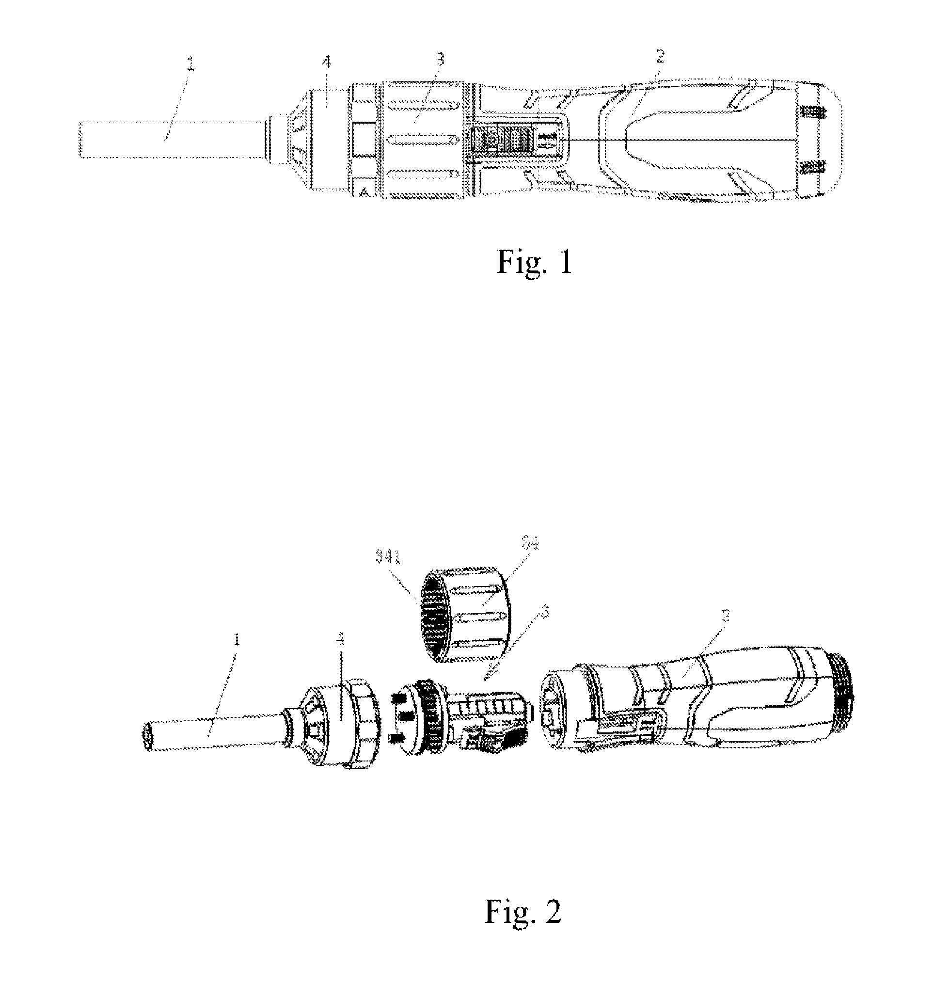
[0022]As shown in FIGS. 1 and 2, the screwdriver of the present invention includes a shaft 1, a handle 2 and a speed increasing mechanism 3. The handle 2 connects the speed increasing mechanism 3, and the handle 2 rotates and rotates in relation to the speed increasing mechanism 3 fixedly connected to the shaft 1 and being rotatable in conjunction with the shaft1, so as to achieve the object of using.

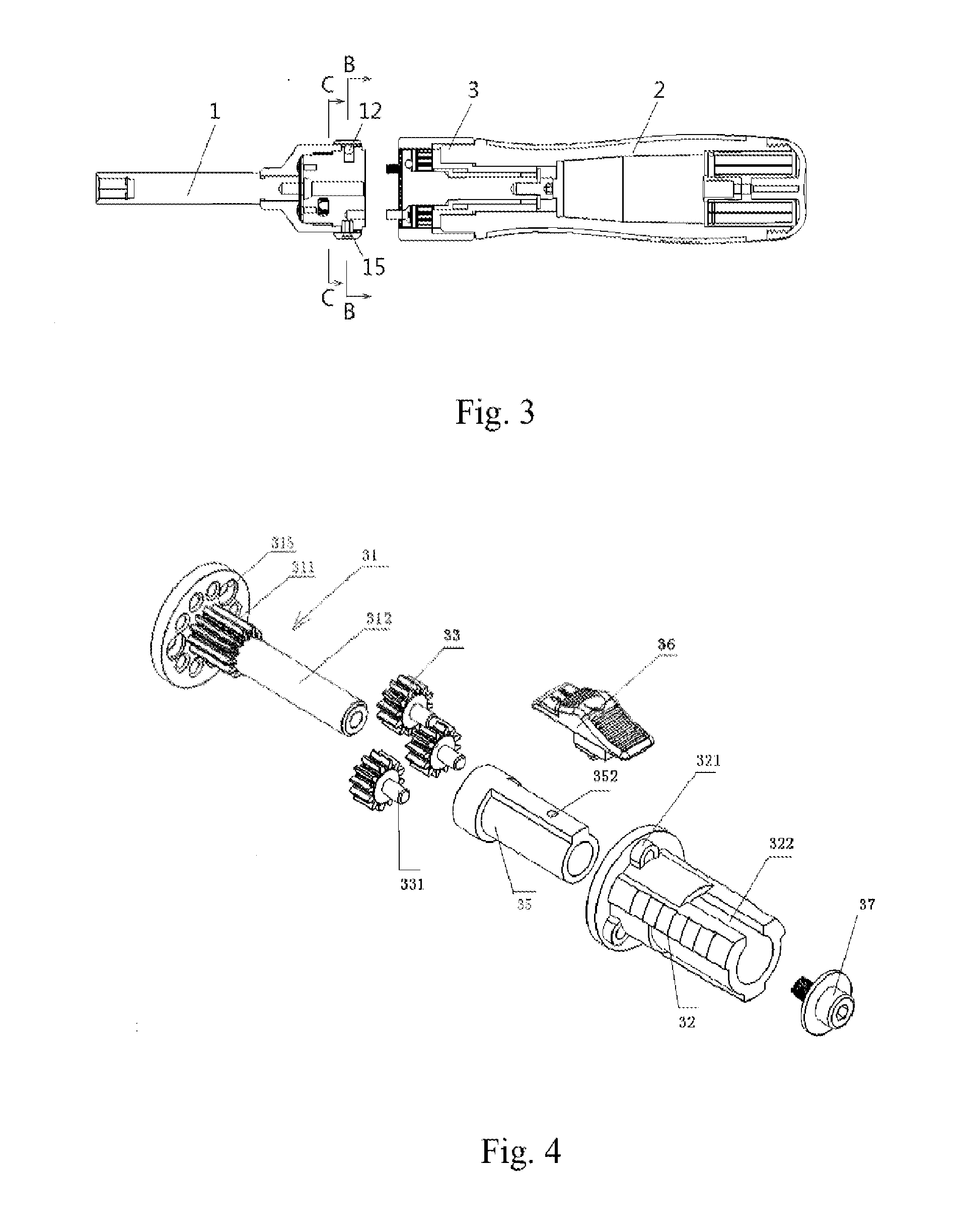
[0023]As shown in FIGS. 4, 5 and 6, speed increasing mechanism 3 includes a central axle 31 connected to the shaft and provided with a toothed part 311 on its periphery, a first member 32 disposed in the interior of the handle, at least one gear 33 connected to the first member, and the gear 33 is disposed at a side part of the central axle and matches with toothed part 311 of the periphery of the central axle 31, and they can engage with each other. The speed increasing mechanism further includes a geared sleeve 34 sheathed outside the gear 33, in which the inner side of the geared sle...


PUM


Abstract

The present invention provides a screwdriver which includes a shaft, a handle and a speed increasing mechanism, in which the speed increasing mechanism includes a central axle connected to the shaft and provided with a toothed part on its periphery, a first member is disposed in the interior of the handle, at least one gear is connected to the first member, and a geared sleeve is sheathed outside the gear, in which the inner side of the geared sleeve has teeth on corresponding positions, engaging with the gear which is disposed at a side part of the central axle and is engaged with the toothed part of the periphery of the central axle. The present invention also includes a locking mechanism addressing the problem of torque being not high.

Description

FIELD OF THE INVENTION[0001]The present invention relates to a tool for screwing a screw and, more particularly, to a screwdriver.DESCRIPTION OF THE PRIOR ART[0002]Screws are tools used for screwing a screw to force it to be in position, including a shaft and a handle. Typically, the handle is manually turned in a full circle, and the shaft rotates in a full circle, until the screw is rotated to a predetermined position, which is very inefficient. Therefore, a speed-increased screwdriver appeared on the market, in which the handle is turned in a full circle, and the shaft may rotate in multiple full circles, thus providing efficiency of using the screwdriver. However, the torque of such screwdriver is not high.[0003]Therefore, the market demand is a screwdriver which is efficient and solves the problem of the torque being not high, as well.SUMMARY OF THE INVENTION[0004]The object of the present invention is to provide a screwdriver with high efficiency for use, which adopts a speed ...

Claims


Application Information

Patent Timeline
IPC IPC(8): B25B17/00B25B15/04
CPCB25B15/04B25B17/00B25B17/02B25B15/02
Inventor WANG, WEIYI
Owner HANGZHOU GREAT STAR TOOLS
Why Eureka
Try Eureka