Partly Disintegrating Plug for Subterranean Treatment Use

a subterranean treatment and plug technology, applied in the direction of fluid removal, sealing/packing, borehole/well accessories, etc., can solve the problems of limited expansion of the enhanced grip, residue,

Active Publication Date: 2015-11-26
BAKER HUGHES INC
View PDF20 Cites 11 Cited by
  • Summary
  • Abstract
  • Description
  • Claims
  • Application Information

AI Technical Summary

Benefits of technology

[0007]A disintegrating plug uses a setting tool to push a swage into the plug body that has external ribs that contact the wall of the surrounding tubular. The ribs retain the body to the surrounding tubular wall with frictional contact. Some leakage may ensue but in fracturing some leakage does not matter if enough volume under the right pressure reaches the formation. The sheared member during the setting comes out with the mandrel that is part of the setting tool. In an alternative embodiment one or more o-rings are used to seal while anchoring is assisted by the hardened insert(s) that can be snap fitted in using rib flexing or that can be a c-ring that is expanded and snapped in. The o-ring(s) are axially spaced from the insert(s).

Problems solved by technology

Additionally hardened materials, while having a benefit to enhance wall penetration into the surrounding tubular for enhanced grip are still limited in their degree of expansion and are not materials that are degradable.
This can then leave residue when degrading other parts of a fracturing plug.

Method used


Image

  • Partly Disintegrating Plug for Subterranean Treatment Use
  • Partly Disintegrating Plug for Subterranean Treatment Use

Examples


Embodiment Construction

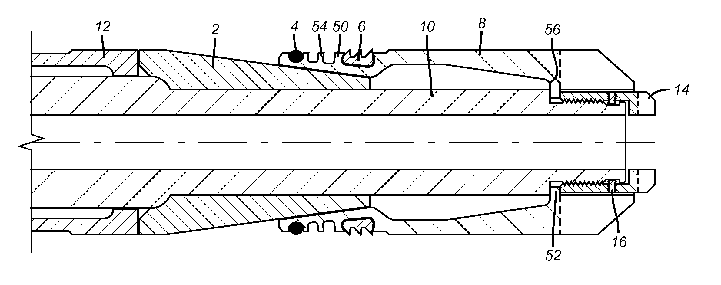
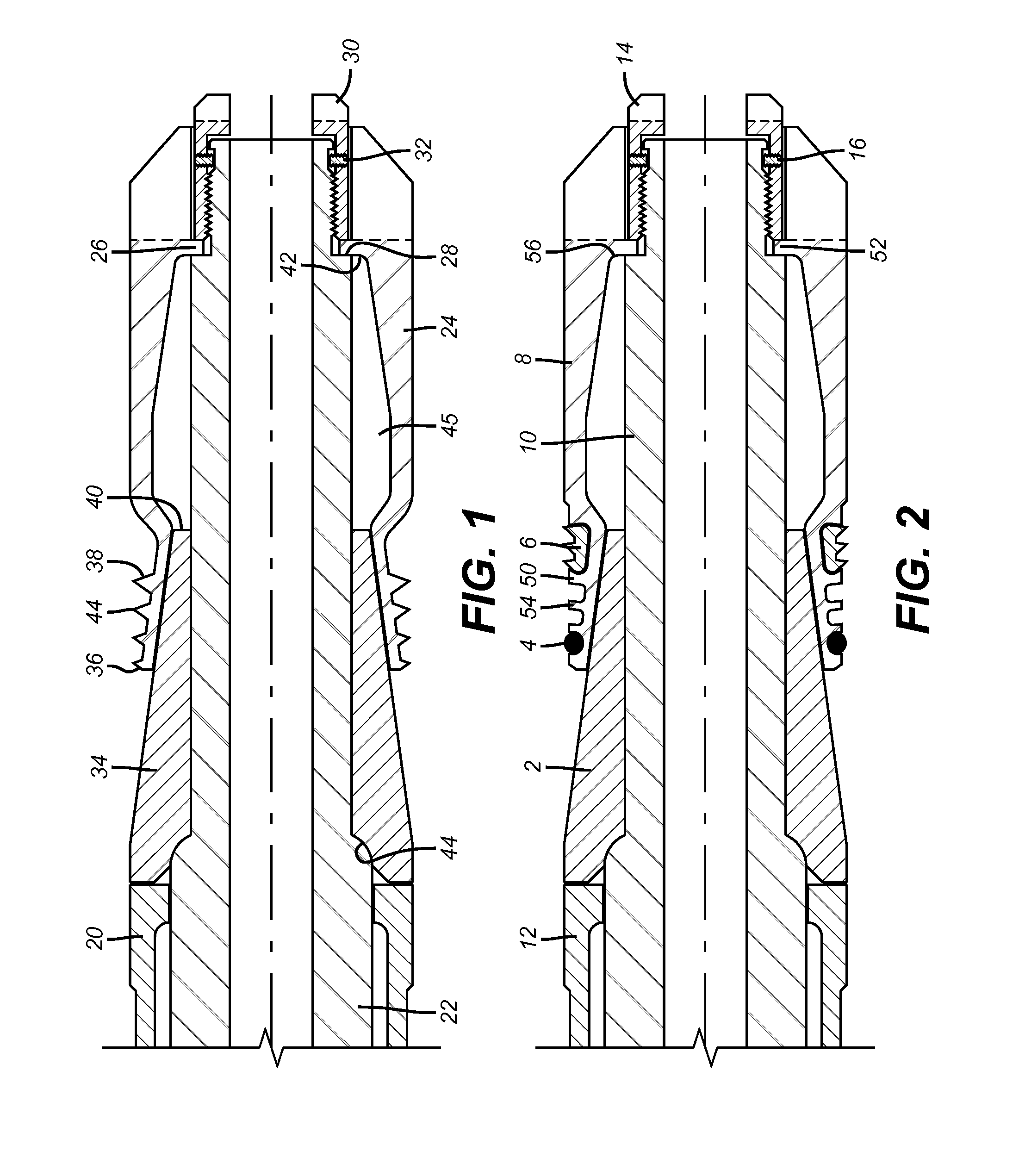
[0010]FIG. 1 shows a setting sleeve 20 and a mandrel 22 that are part of a wireline setting tool that is not shown. The mandrel 22 supports the plug 24 due to tab 26 being positioned on shoulder 28 and retained there by retaining nut 30 which is further retained by set screw 32. During the setting the wireline setting tool such as an E-4 made by Baker Hughes Incorporated of Houston, Tex. pushes down on sleeve 20 while pulling up on mandrel 22 so that the cone 34 ramps out the top end 36 of the plug 24. Near the top end 36 are a series of ribs 38 made preferably from a disintegrating material when exposed to certain well conditions or fluids. One such material is a controlled electrolytic material or CEM as described in US Publication 2011 / 0136707 and related applications filed the same day. The related applications are incorporated by reference herein as though fully set forth. As a result when the proper conditions are obtained the plug 24 will fully disintegrate as it constituent ...


PUM


Abstract

A disintegrating plug uses a setting tool to push a swage into the plug body that has external ribs that contact the wall of the surrounding tubular. The ribs retain the body to the surrounding tubular wall with frictional contact. Some leakage may ensue but in fracturing some leakage does not matter if enough volume under the right pressure reaches the formation. The sheared member during the setting comes out with the mandrel that is part of the setting tool. In an alternative embodiment one or more o-rings are used to seal while anchoring is assisted by the hardened insert(s) that can be snap fitted in using rib flexing or that can be a c-ring that is expanded and snapped in. The o-ring(s) are axially spaced from the insert(s).

Description

FIELD OF THE INVENTION[0001]The field of the invention is barrier plugs for use in subterranean locations for formation treatment and more particularly plugs that substantially disintegrate when the treatment has ended.BACKGROUND OF THE INVENTION[0002]In certain types of treatments such as fracturing, a series of barriers with ball seats are used for the purpose of sequentially isolating intervals that have already been fractured so that the next interval uphole can be perforated and fractured. Typical of such plug devices is Us2013 / 0000914. Here sleeves are expanded that have an external seal and a lower end ball seat. At the end of the fracturing operation all the sleeves that were used have to be milled out.[0003]US 2014 / 0014339 shows the use of a plug with an external rubber seal that is expanded with a swage moved by a wireline setting tool where the swage has a ball seat and is made of a disintegrating material. The design uses a shear device to the setting tool mandrel that r...

Claims


Application Information

Patent Timeline
Patent Type & Authority Applications(United States)
IPC IPC(8): E21B33/12
CPCE21B33/1208E21B23/01E21B33/12
Inventor HERN, GREGORY L.OBERG, LEVI B.
Owner BAKER HUGHES INC
Why Eureka
Try Eureka