Threaded pipe joint

a pipe joint and threaded technology, applied in the direction of threaded joints, pipes/joints/fittings, hose connections, etc., can solve the problems of high pressure peaks, deformation of the joint, and extremely dangerous joint use of lubricants, so as to reduce the pressure of the lubricant of the joint and excellent performance levels

Inactive Publication Date: 2005-06-14
TENARIS CONNECTIONS
View PDF19 Cites 57 Cited by
  • Summary
  • Abstract
  • Description
  • Claims
  • Application Information

AI Technical Summary

Benefits of technology

[0011]The object of the present invention is to provide a joint that presents, after tightening, reduced pressures in the lubricant of the joint and has excellent performance levels.
[0012]Another object of the invention is to provide a joint maintaining excellent performance even with excessive use of lubricant, which can result from an incorrect application by users when being applied in operation.
[0013]Another object of the present invention is to provide a joint easy to assemble and to tighten in operational conditions during installation and that can therefore be used with automatic plants.
[0014]Another object of the present invention is to provide a joint that can be manufactured and used both with carbon steels and with corrosion-resistant alloys, such as stainless steels with a high content of chrome or Chrome / Nickel alloys, in which the presence of chromium favours the seizure of the sealing surfaces and therefore requires particular precautions in planning and execution.
[0017]Moreover, the choice of the particularly low value, and substantially lower than the length of the notch, of the distance in the axial direction between the point of first contact between the respective sealing surfaces of the ends of the male element and the female element, during make-up of the joint, and the final position of screwing of the sealing surfaces, allows for the formation of the seal to be delayed with the result that the closure of the notch that functions as a reservoir for the dope or grease for the joint is delayed and the amount of dope that remains trapped is reduced.
[0020]In this way, both a reduction of the pressure of the grease in the joint and a better behaviour in forming the seal between the two elements of the joint are achieved, yet maintaining the high structural performance level that allows it to be used even in the presence of high stress, particularly in an axial direction, thus making the use of it advantageous for particular applications.

Problems solved by technology

However, if no appropriate measures are taken, the use of lubricants can be extremely dangerous for the integrity of the joint.
However, as the lubricant is incompressible, extremely high pressure peaks occur that are extremely harmful, that can cause a deformation of the joint, in particular of the metal / metal sealing surfaces.
In order to solve this problem, the U.S. Pat. No. 4,830,411 proposes to increase the space between the threads to house the lubricant; however, it has been noted that when tightening the joint, very high pressure peaks are still reached, even if, in time, the lubricant can flow and the pressure therefore decreases, and therefore the problems due to the pressure peaks remain unsolved.
The document, on the other hand, has not solved the problem caused by the high-pressure peaks that develop upon tightening, in particular due to the non-optimal design of the reservoir, for which only the interval in which the length can vary depending on the thread rate is suggested.
In this case, however, the problem of the development of high-pressure peaks during make-up of the joints has not been overcome in a satisfactory manner.
These solutions, though having proved to be efficient from the-point of view of the reduction of the peaks of pressure in the lubricant, are found to be weak from the point of view of the seal under high axial tensile loads because of the high taper of the sealing surfaces.
Therefore, up to now, the problem of having a lubricated joint easy to assemble, which can be completely tightened without negative collateral effects and which ensures a seal even under strong axial tensile loads of has not been solved favourably.

Method used


Image

  • Threaded pipe joint
  • Threaded pipe joint
  • Threaded pipe joint

Examples


Embodiment Construction

[0026]With reference to the figures, a joint according to the present invention is now described as a non-limiting example.

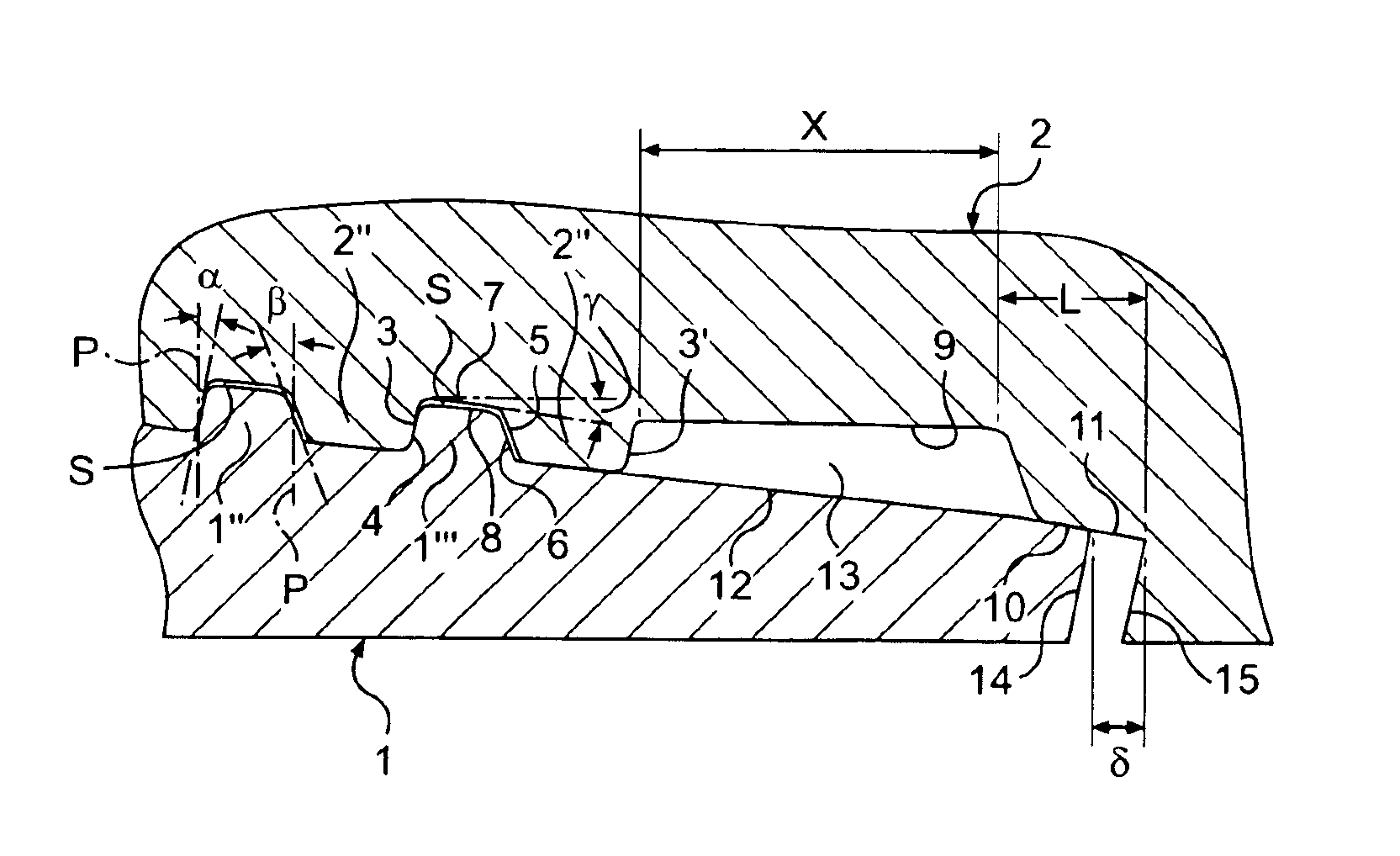
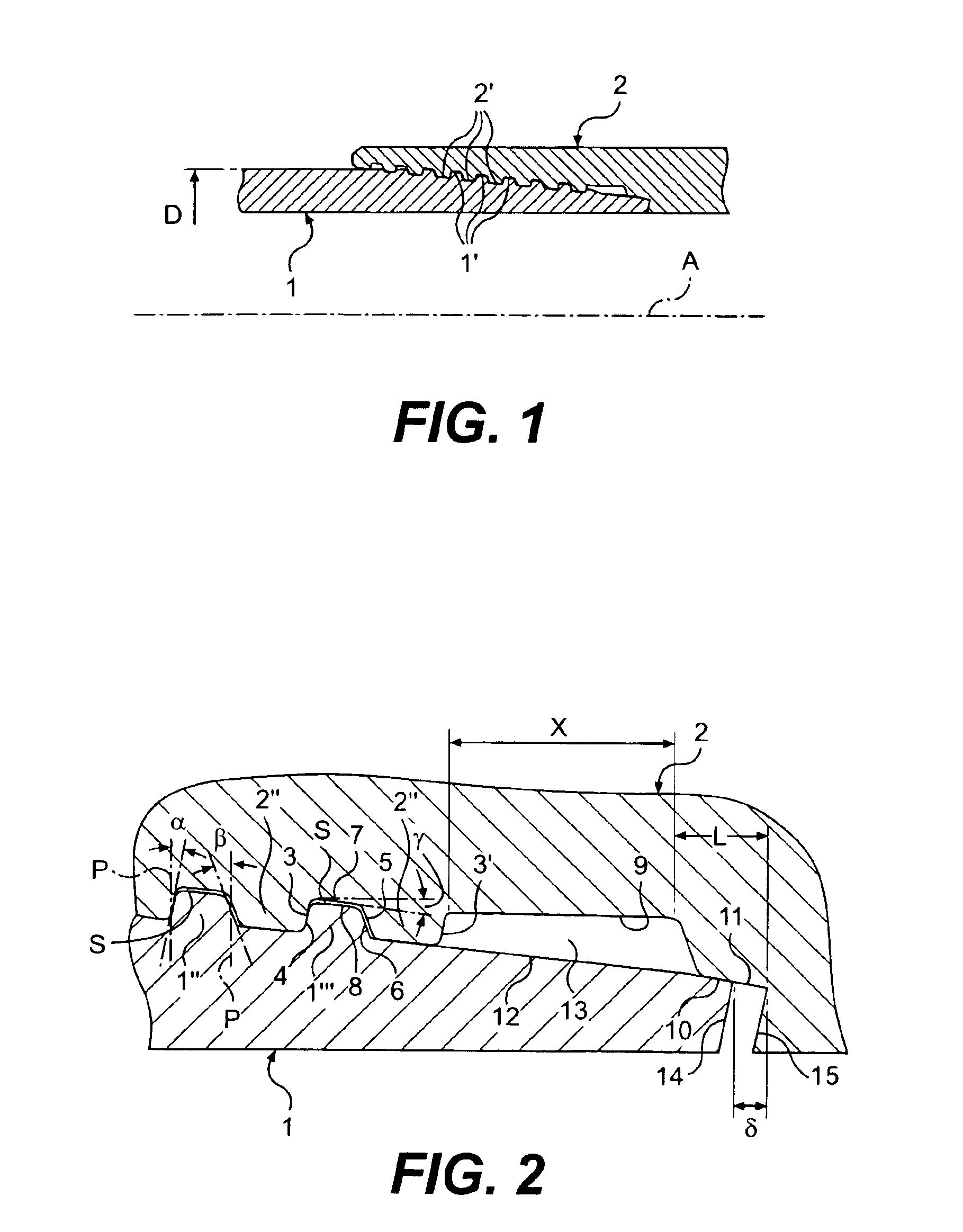
[0027]The joint according to the present invention, used to join pipes with a nominal diameter D, comprises a male element carrying an external thread 1′, and a female element 2 bearing an internal thread 2′. The common axis of the pipe and the male and female elements is indicated with A.

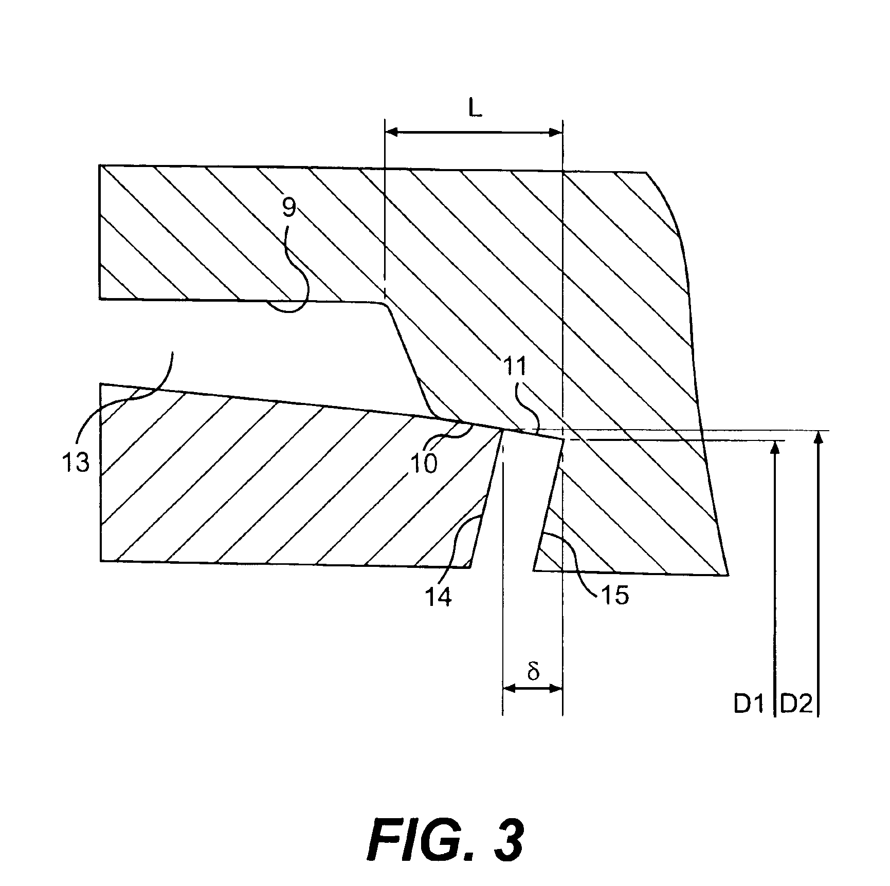
[0028]All the teeth 1″,1′″ and 2″ of the threads 1′ and 2′ respectively have lead-in flanks, respectively 6 and 5, inclined towards the left, in the sense of FIG. 2, with respect to a perpendicular P to the axis A of an angle β between 10° and 25°, and load flanks, 4 and 3 respectively, inclined, in the sense of FIG. 2, with respect to a perpendicular P to the axis A of an angle α between −4° and 3°. The peaks 8 and the roots 7 of the teeth are inclined with regard to the axis A of the pipe of an angle γ of a value between 0° and 4°.

[0029]The inner part of the male element 1 co...


PUM


Abstract

Threaded pipe joint comprising a male element (1) and a female element (2), threaded and provided with respective complementary sealing surfaces, which define, when screwed together, a notch (13) formed on the female element (2) of a predetermined length (X), and a space (7, 8) between the threads of predetermined section (S), forming reservoir to house the joint lubricant, which comes out of the volume between the threads of the female (2) and male (1) elements during the tightening of the joint.

Description

FIELD OF INVENTION[0001]The present invention relates to a joint for drilling pipes and more precisely, a threaded joint for joining pipes used in the search and exploitation of hydrocarbons, in particular pipes for casing of wells, either for oil and / or gas, exploration and / or pumping. The joints are of the male / female type, in which a particular design of the thread and the sealing surfaces together with a reservoir to collect the lubricant in excess ensures avoidance of pressure peaks caused by the lubricant during tightening and an excellent sealing capacity even under high axial tensile loads. Such pipes can be used both for casings for drilling wells and as strings for gas or oil pumping.STATE OF THE ART[0002]In the natural gas and oil extraction industry, in the preliminary drilling phase, drilling is carried out either on the sea bed or on land, until the petroleum or gas reservoir is reached, which may even lay at depths of thousands of metres. During such preliminary phase...

Claims


Application Information

Patent Timeline
Patent Type & Authority Patents(United States)
IPC IPC(8): F16L15/00F16L15/04
CPCF16L15/004
Inventor CARCAGNO, GABRIEL E.PINA, GIUSEPPE DELLATOSCANO, RITA G.PODRINI, ANTONIO
Owner TENARIS CONNECTIONS
Why Eureka
Try Eureka