Connector, a connector assembly and a connecting method

a technology of connectors and connectors, applied in the direction of connection, electrical apparatus, coupling device connection, etc., can solve the problems of improper connection of mating connectors, insufficient space at the connection surface, and inability to extend the entrance of the accommodating portion of such a connector along the terminal

Inactive Publication Date: 2010-10-12
SUMITOMO WIRING SYST LTD
View PDF12 Cites 51 Cited by
  • Summary
  • Abstract
  • Description
  • Claims
  • Application Information

AI Technical Summary

Benefits of technology

[0014]The nut cover may have a cover main body, and at least one plate piece may extend from the cover main body substantially along a connecting direction. The plate pieces may project from the cover main body substantially along the connecting direction at a position right below each engaging piece. Thus, spaces are defined between the plate pieces and the engaging pieces for permitting resilient deformations of the engaging pieces.

Problems solved by technology

However, the entrance to the nut accommodating portion of such a connector cannot extend along the terminal.
However, this construction may not permit sufficient space at the connection surface for an inverted insertion preventing structure to prevent a connection if the mating connector is in an improper orientation.
Thus, the mating connector may be connected in an improper orientation.

Method used


Image

  • Connector, a connector assembly and a connecting method
  • Connector, a connector assembly and a connecting method
  • Connector, a connector assembly and a connecting method

Examples


Embodiment Construction

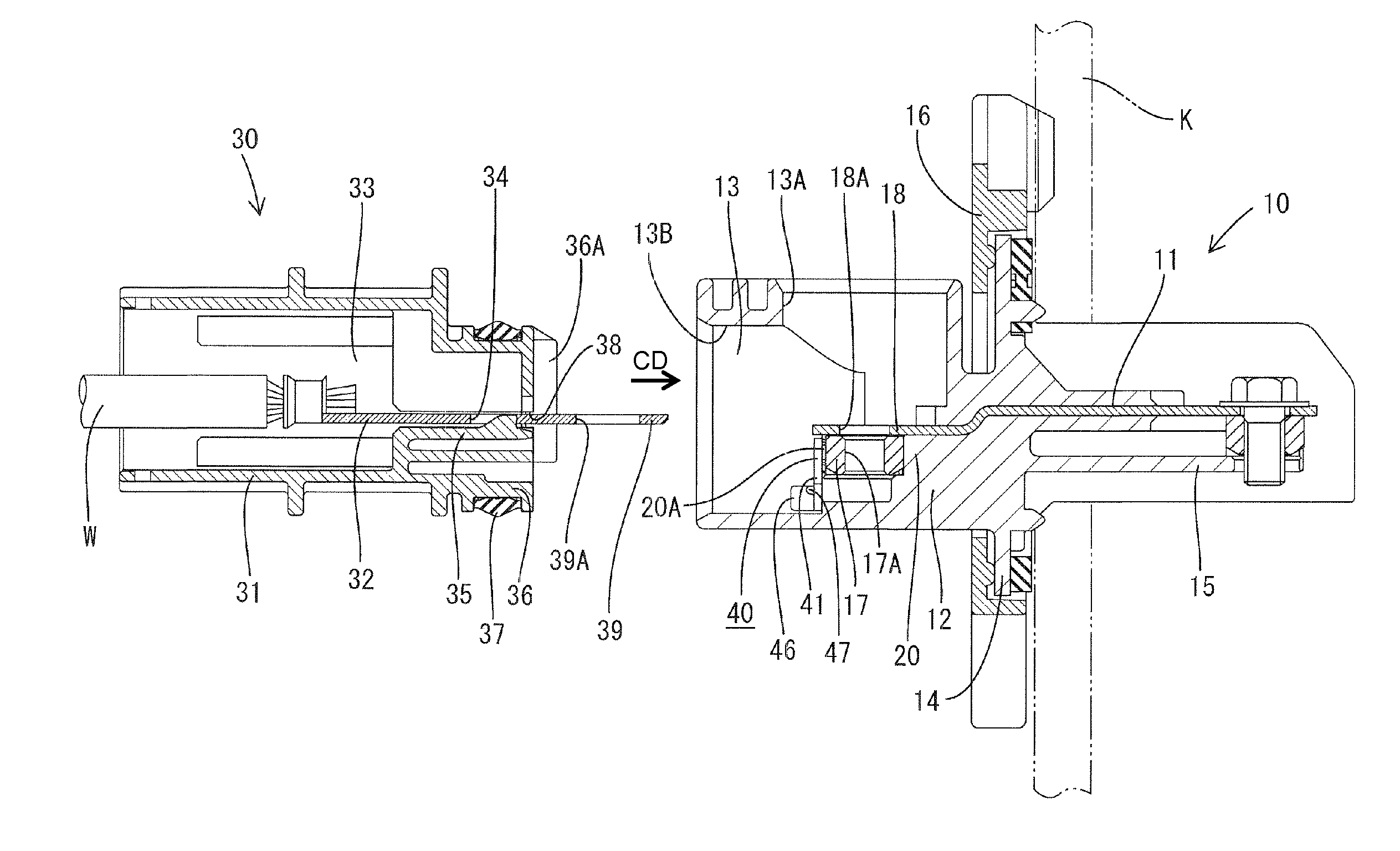
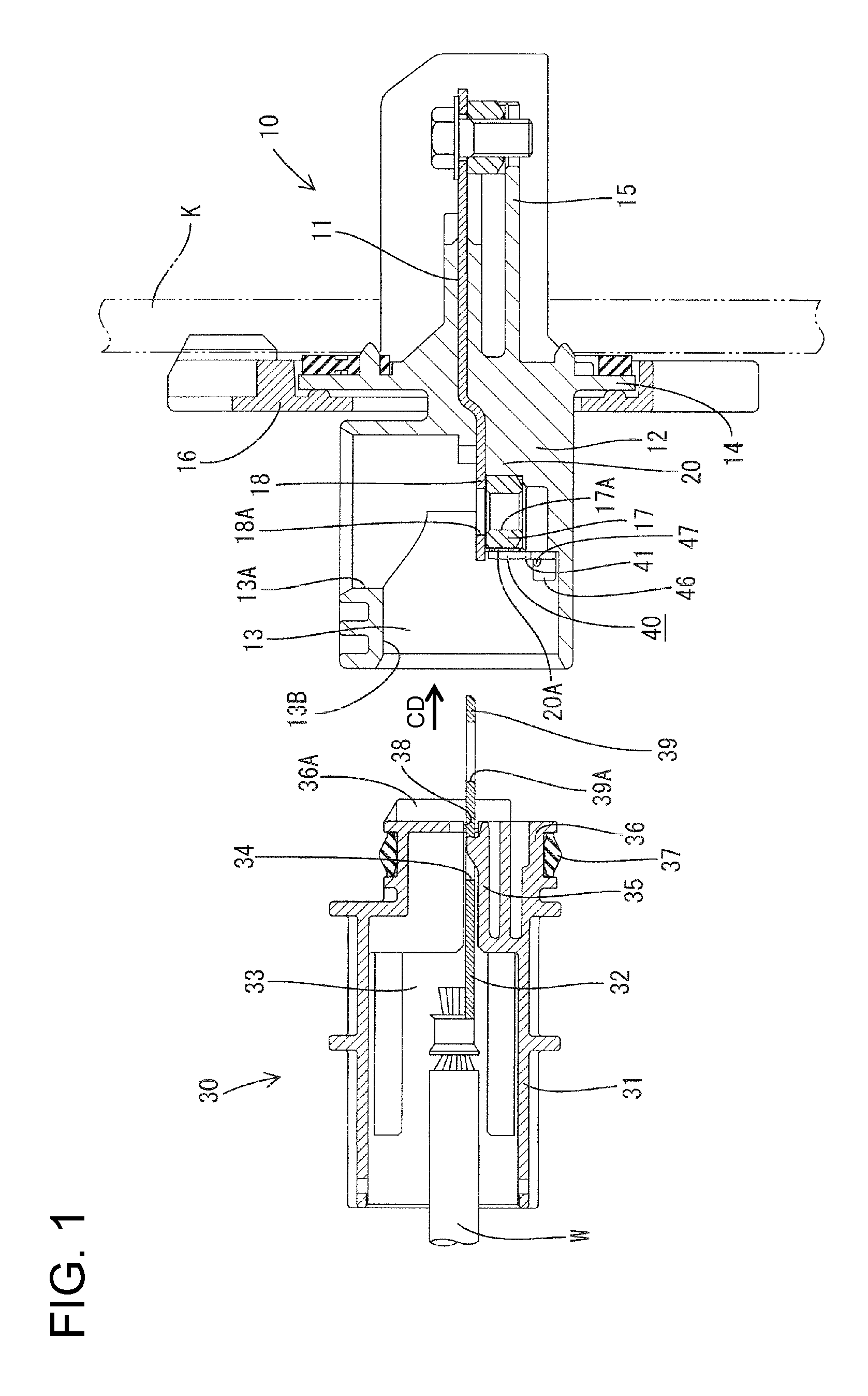
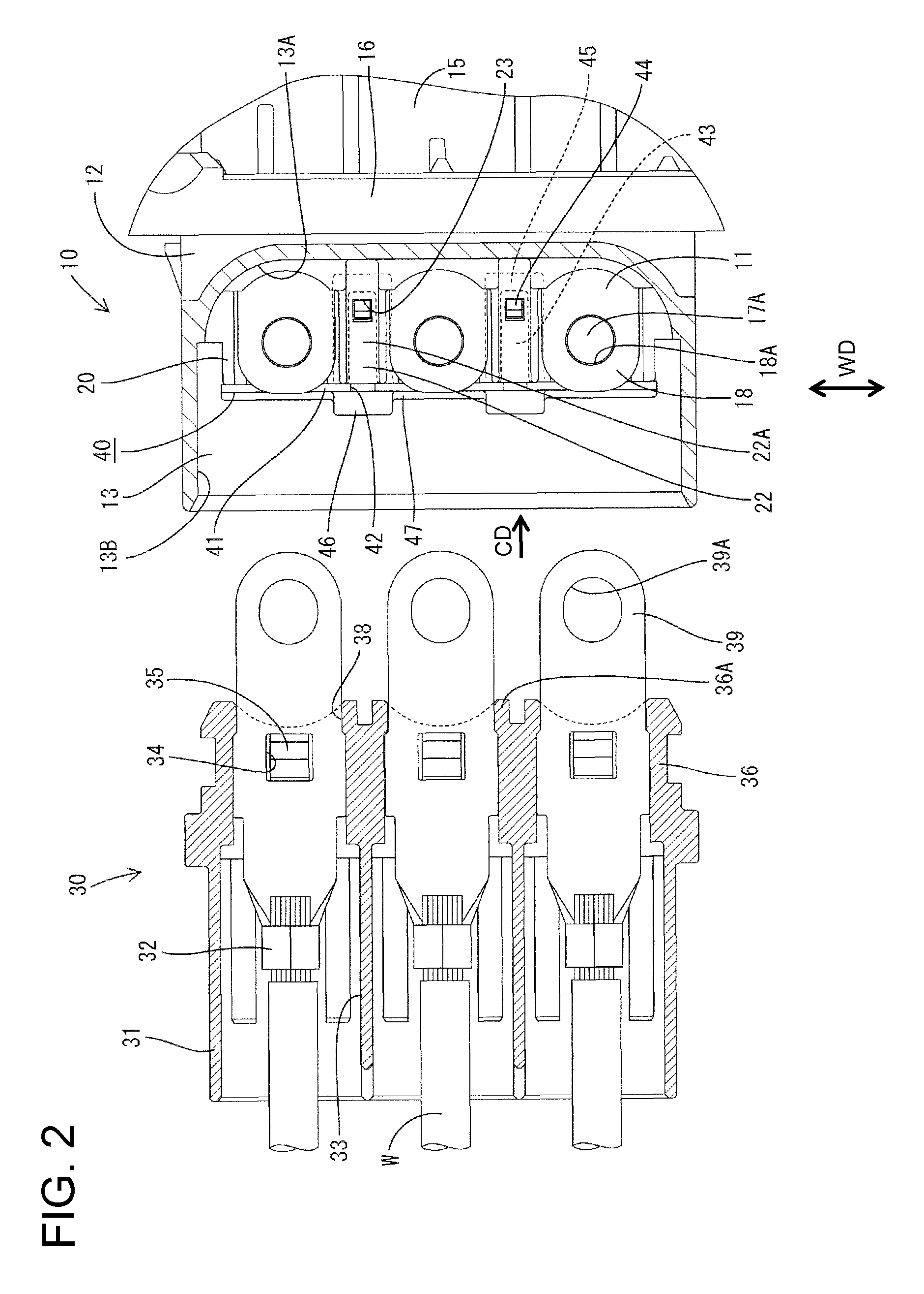
[0032]A connector assembly in accordance with the invention is intended for supplying power to an unillustrated device (e.g. a junction box, a load such as a motor, an inverter or the like that may be installed in a hybrid vehicle). The connector assembly is comprised of first and second connectors 10 and 30 that are connectable with each other. In the following description, ends of the connectors 10, 30 that are to be connected are referred to as the front ends and upper and lower sides in FIG. 1 are referred to as upper and lower sides.

[0033]The second connector 30 includes a second housing 31 made e.g. of synthetic resin. Cavities 33 are arranged side by side in the second housing 31 and second terminals 32 fixed to ends of wires W (see FIG. 2) are inserted respectively into the cavities 33 from behind. Locking lances 35 are provided at front end portions of the cavities 33 and engage locking holes 34 of the second terminals 32 to retain the second terminals 32 in the cavities 33...


PUM


Abstract

A connector is provided with terminals (11) to be connected with terminals (32) of a mating connector (30) by bolting and a nut accommodating portion (20) for accommodating nuts (17) for bolting. An entrance (20A) enabling the insertion and withdrawal of the nuts (17) is formed at a connection surface side of the nut accommodating portion (20) with the mating connector. A nut cover (40) for preventing the nuts (17) from coming out through the entrance (20A) is detachably attachable to the nut accommodating portion (20) and includes inverted insertion preventing portions (46) for permitting a connection with the mating connector (30) when the mating connector (30) is in a proper orientation while coming into contact with the mating connector (30) to prevent the connection when the mating connector (30) is not in the proper orientation.

Description

BACKGROUND OF THE INVENTION[0001]1. Field of the Invention[0002]The invention relates to a connector in which a terminal is connected by bolting and to a connector assembly.[0003]2. Description of the Related Art[0004]Japanese Unexamined Patent Publication No. 2006-31962 discloses a connector with a terminal that can be bolted into connection with a terminal of a mating connector. The connector has a nut accommodating portion that accommodates a nut for bolting. An entrance extends into the nut accommodating portion and extends along the terminal so that the nut can be inserted and withdrawn. The nut is inserted into the nut accommodating portion and then the terminal is inserted into the housing. Thus, the terminal closes the entrance of the nut accommodating portion and prevents the nut from coming out.[0005]A terminal and a housing of a connector can be formed integrally by insert molding. However, the entrance to the nut accommodating portion of such a connector cannot extend al...

Claims


Application Information

Patent Timeline
Patent Type & Authority Patents(United States)
IPC IPC(8): H01R13/621
CPCH01R4/302H01R4/34H01R11/12H01R13/5202
Inventor SAKAKURA, KOUJIAKUTA, DAISUKE
Owner SUMITOMO WIRING SYST LTD
Why Eureka
Try Eureka