
Tank Liner Clamp System
a technology of liner clamp and clamping plate, which is applied in the direction of snap fasteners, buckles, transportation and packaging, etc., can solve the problems of time and labor, difficult to remove or install, and use of tools
- Summary
- Abstract
- Description
- Claims
- Application Information
AI Technical Summary
Benefits of technology
Problems solved by technology
Method used
Image

Examples
Embodiment Construction
A. Overview.
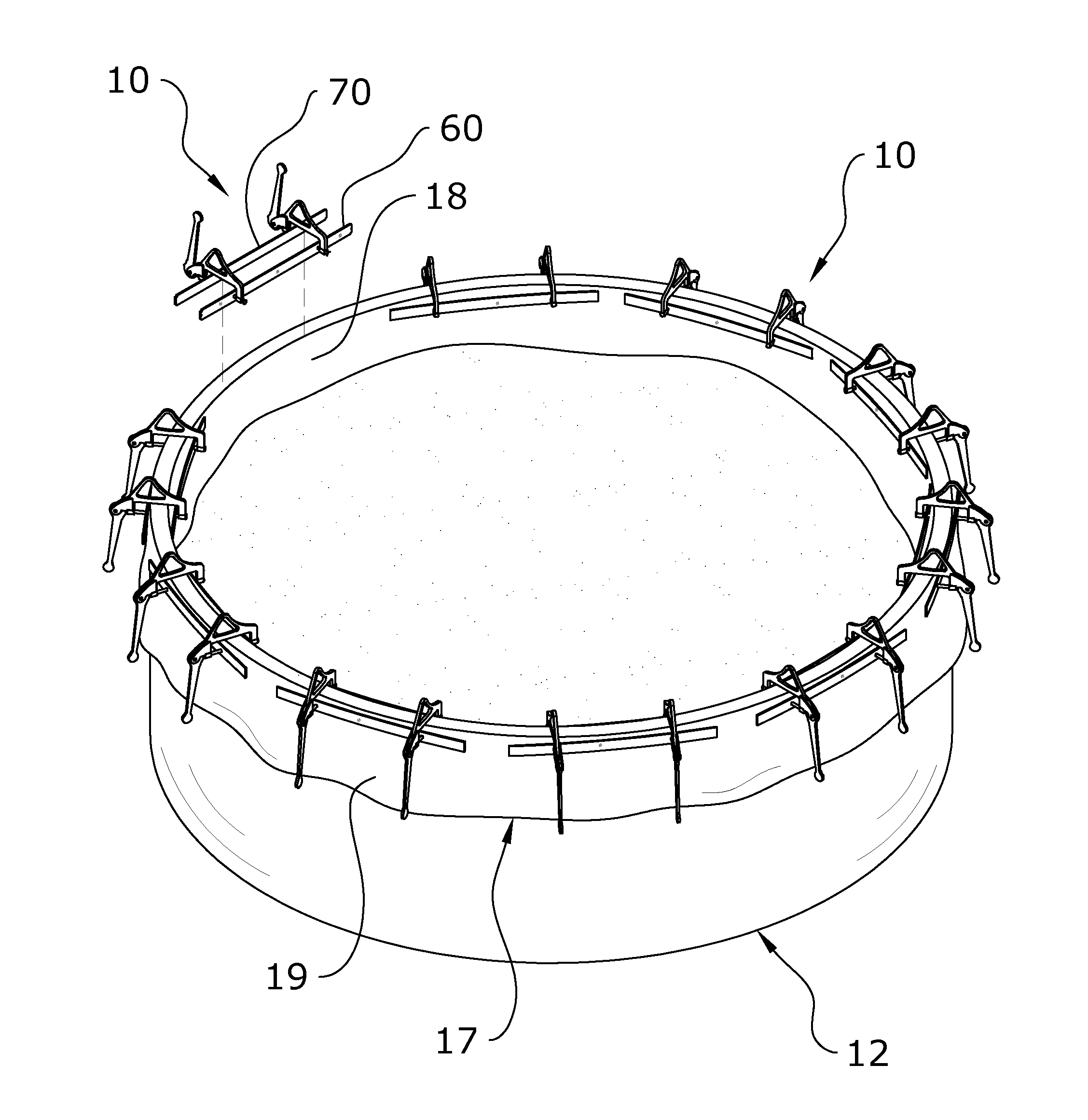
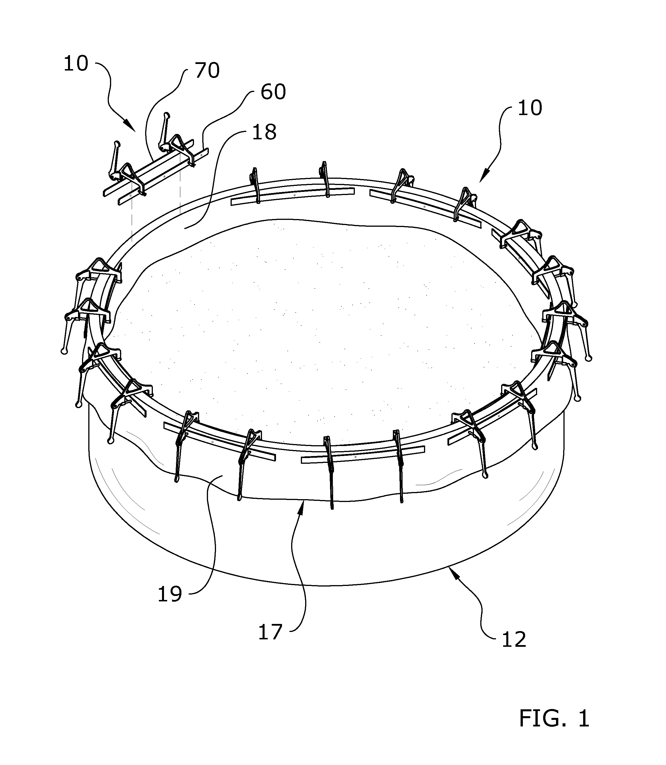
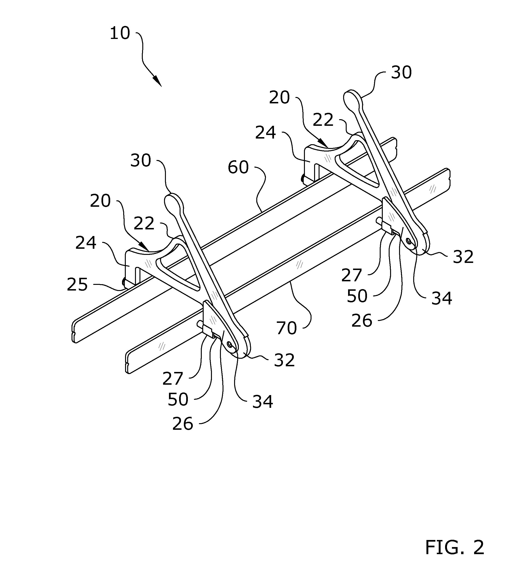
[0026]Turning now descriptively to the drawings, in which similar reference characters denote similar elements throughout the several views, FIGS. 1 through 9c illustrate a tank liner clamp system 10, which comprises a clamp unit 20, a first member 60 and a second member 70 slidably connected to the clamp unit 20, and a clamping handle 30 having a cam 32 pivotally connected to the clamp unit 20. The first member 60 includes a biasing member 44 to bias the first member 60 inwardly towards the second member 70. The clamping handle 30 is pivoted causing the cam 32 to engage and inwardly force the second member 70 towards the first member 60.
B. Clamp Unit.
[0027]One or more clamp units 20 are connected to the first member 60 and the second member 70 to force the members 60, 70 towards one another. As shown in FIGS. 1-4 and 6-8b of the drawings, it is preferable to have two clamp units 20 connected to the members 60, 70 at opposite end portions of the members 60, 70. However, ...
PUM
 Abstract
Description
Claims
Application Information