Devices and Systems For Real-Time Experience Sharing

a technology of real-time experience and devices, applied in static indicating devices, instruments, optics, etc., can solve the problem that no one truly replicates the experience of another individual

Inactive Publication Date: 2015-12-24
FILTREST
View PDF4 Cites 14 Cited by
  • Summary
  • Abstract
  • Description
  • Claims
  • Application Information

AI Technical Summary

Benefits of technology

This patented technology allows two devices (the primary) can be attached together without affecting their appearance when worn separately. One device has an eye-shaped screen that covers up at least part of its visual area while another device only partially occupies it. When wearing this combination they create a three dimensional (3D) immersive virtual reality world with 360 degrees views around us.

Problems solved by technology

The technical problem of this patent text is that none of the existing devices can provide a truly immersive virtual reality experience that replicates the experience of another individual.

Method used


Image

  • Devices and Systems For Real-Time Experience Sharing
  • Devices and Systems For Real-Time Experience Sharing
  • Devices and Systems For Real-Time Experience Sharing

Examples


Embodiment Construction

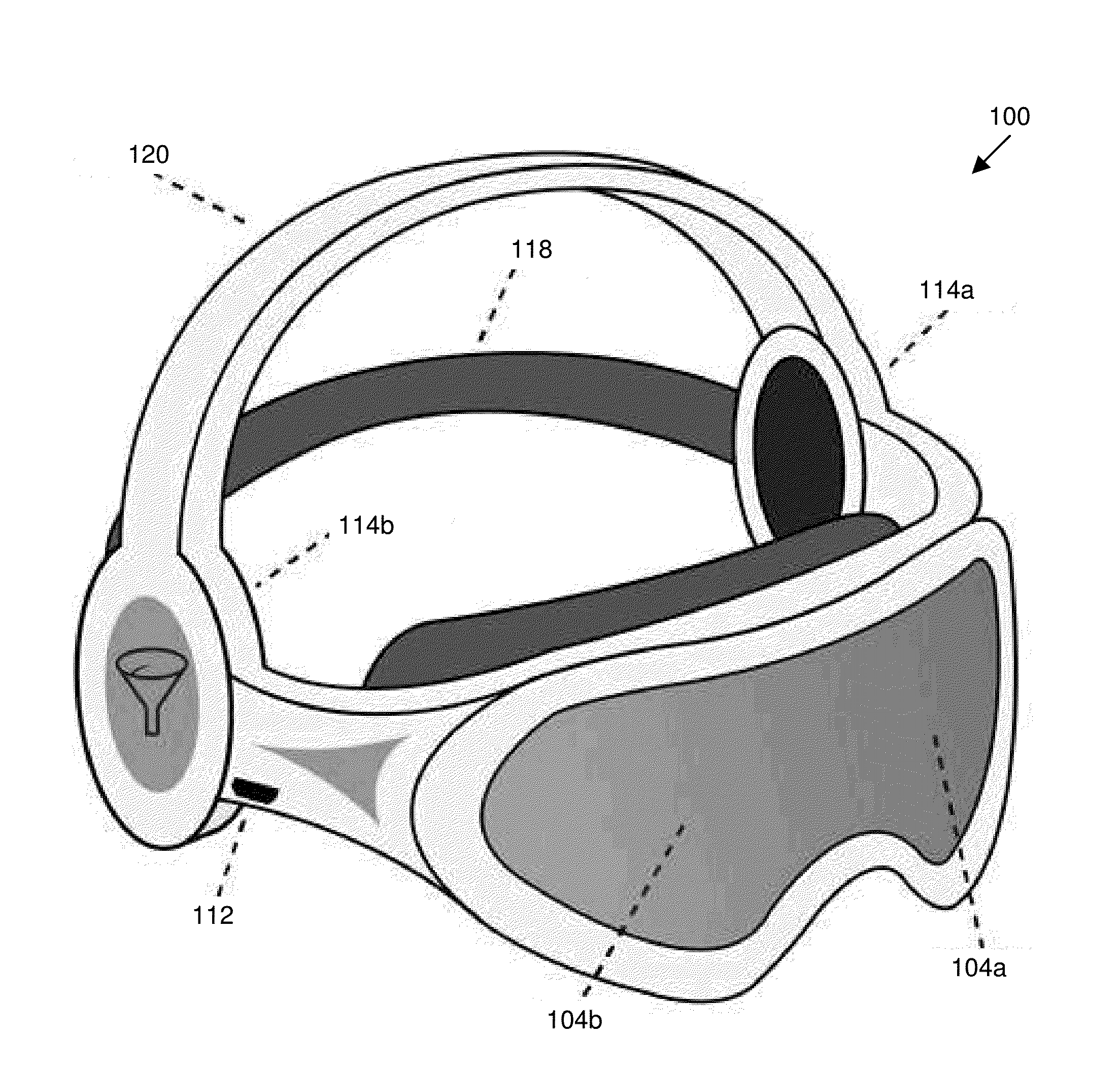
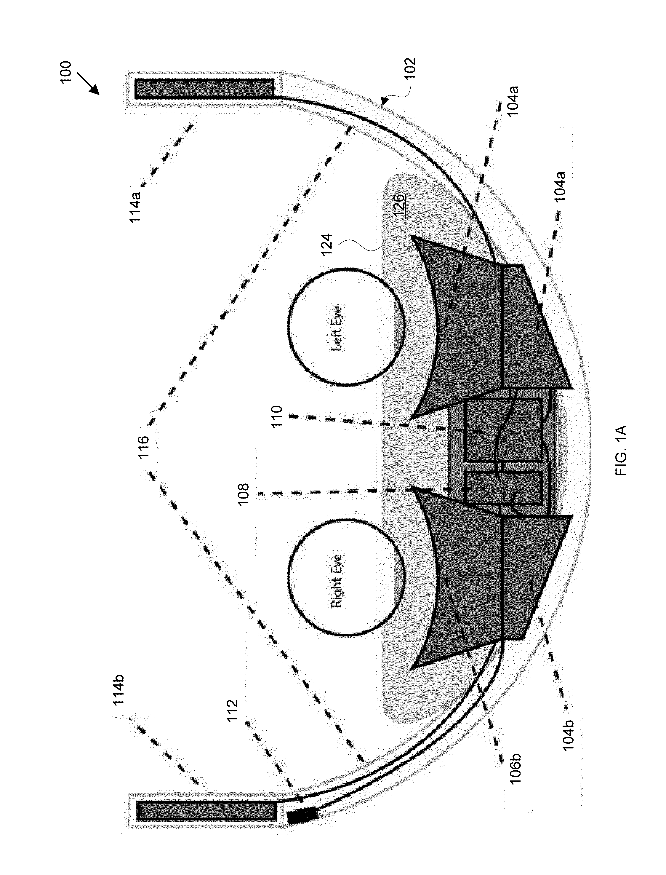
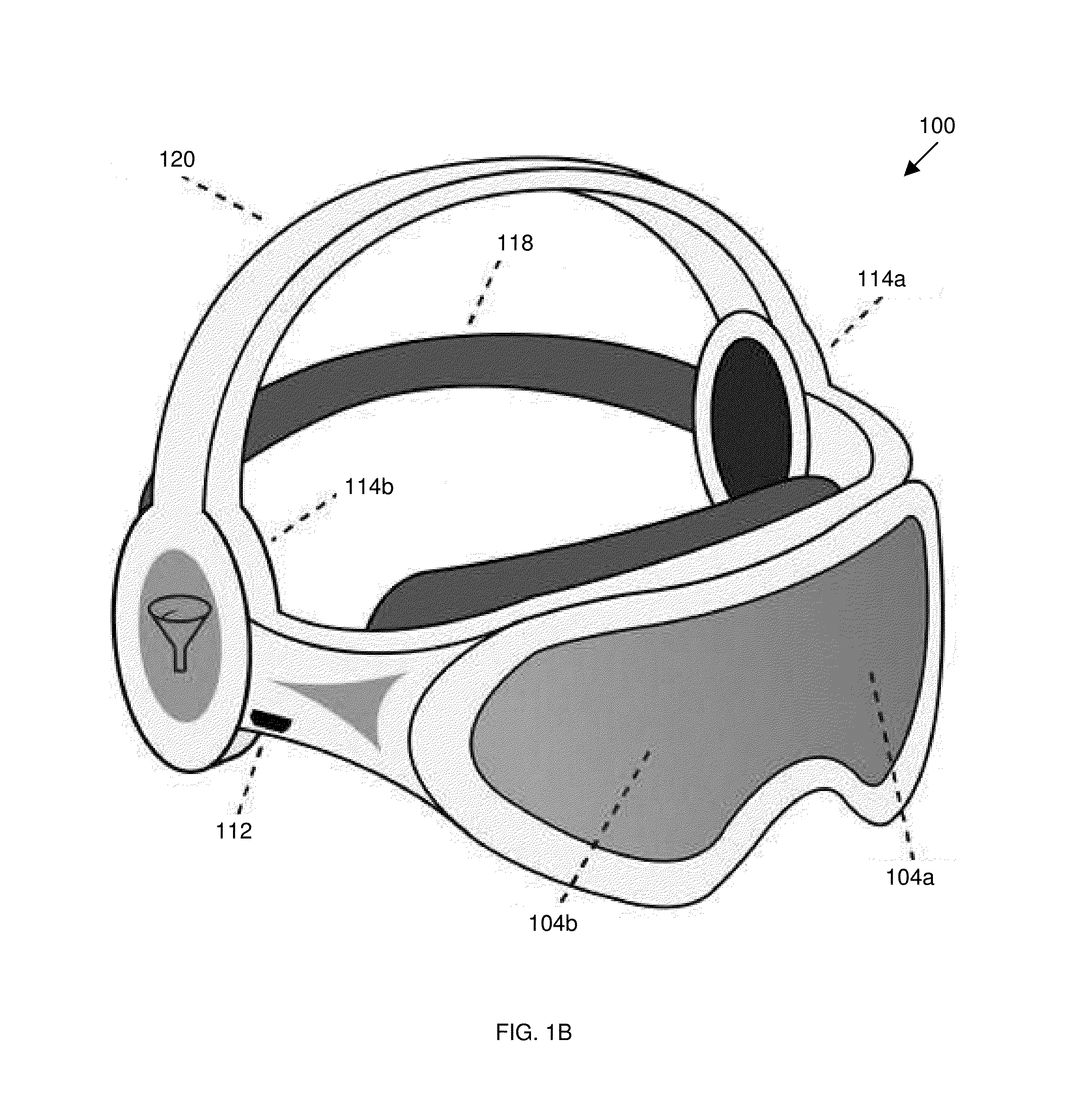
[0023]Headset devices in accordance with the present invention can be used to share a first user's visual experience with a second, remotely located, user. An exemplary headset includes a pair of digital cameras mounted on a headset in a spaced relationship corresponding to a spaced relationship of human eyes. As the wearer wears the headset, the cameras capture video input, and create corresponding video signals—one corresponding to a wearer's left eye, the other corresponding to the wearer's right eye.

[0024]The headset further defines a bay positioned to cover and enclose the wearer's eyes and obscure the wearer's field of view. A pair of display screens are mounted within the bay in a spaced relationship corresponding to a spaced relationship of human eyes—one corresponding to a wearer's left eye, the other corresponding to the wearer's right eye. Preferably, each display screen is a high resolution display, such as a 1920×1080 HD display.

[0025]The video signal captured by the le...


PUM


Abstract

One aspect of the invention provides a device including: a headset defining a bay positioned to cover and enclose the wearer's eyes and obscure the wearer's field of view; one or more screens mounted within the bay; a pair of digital cameras mounted to the headset for capturing video images outside the bay, said pair of digital cameras positioned in a spaced relationship corresponding to a spaced relationship of human eyes; a viewed image display circuit programmed to display a first video signal captured by a first one of said pair of digital cameras and a second video signal captured by a second one of said pair of digital cameras on said one or more display screens to provide a stereographic viewing experience to a wearer; and a transmitter programmed to transmit the first and second video signals to a remote video-sharing device.

Description


Claims


Application Information

Patent Timeline
Owner FILTREST
Why Eureka
Try Eureka