Multiple tube bank heat exchange unit with manifold assembly

Active Publication Date: 2016-01-07
CARRIER CORP
View PDF5 Cites 8 Cited by
  • Summary
  • Abstract
  • Description
  • Claims
  • Application Information

AI Technical Summary

Problems solved by technology

However, to connect the two slabs in fluid flow communication in other

Method used


Image

  • Multiple tube bank heat exchange unit with manifold assembly
  • Multiple tube bank heat exchange unit with manifold assembly
  • Multiple tube bank heat exchange unit with manifold assembly

Examples


Example

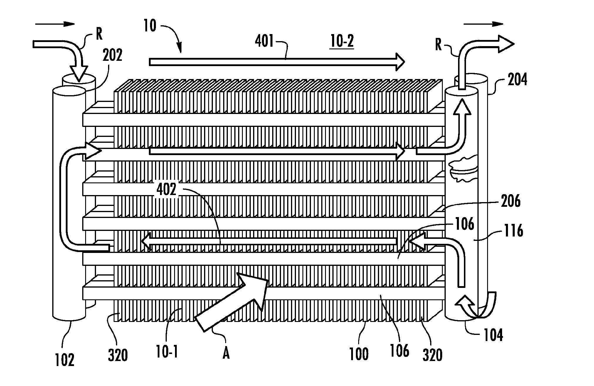
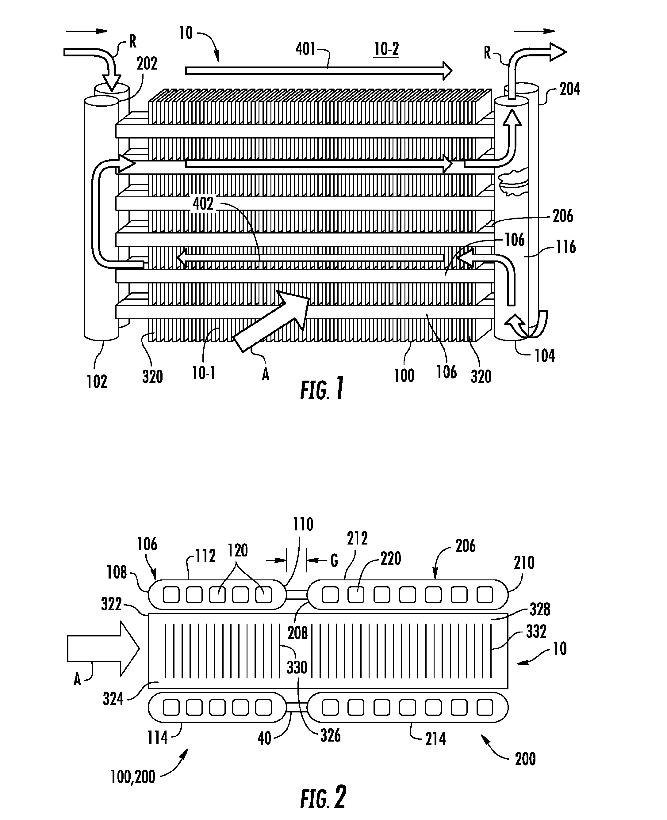
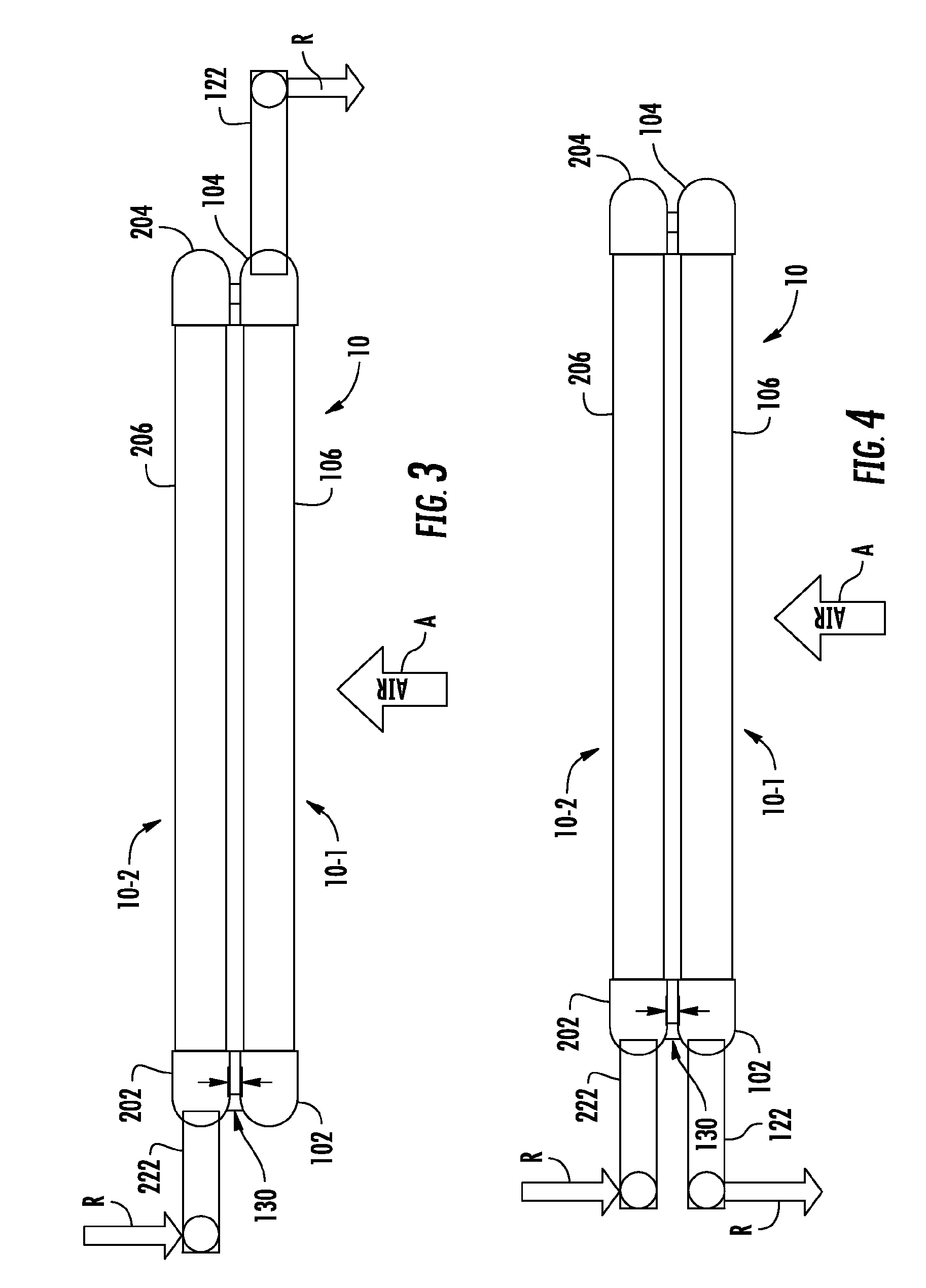
[0029]An exemplary embodiment of a multiple bank flattened tube finned heat exchanger unit in accordance with the disclosure, generally designated 10, is depicted in perspective illustration in FIG. 1. As depicted therein, the multiple bank flattened tube finned heat exchanger 10 includes a first tube bank 100 and a second tube bank 200 that is disposed behind the first tube bank 100, that is downstream with respect to air flow, A, through the heat exchanger. The first tube bank 100 may also be referred to herein as the front heat exchanger slab 100 and the second tube bank 200 may also be referred to herein as the rear heat exchanger slab 200.

[0030]The first tube bank 100 includes a first manifold 102, a second manifold 104 spaced apart from the first manifold 102, and a plurality of heat exchange tube segments 106, including at least a first and a second tube segment, extending longitudinally in spaced parallel relationship between and connecting the first manifold 102 and the sec...


PUM

PropertyMeasurementUnit
Thicknessaaaaaaaaaa
Flow rateaaaaaaaaaa
Volumeaaaaaaaaaa

Abstract

A multiple bank, flattened tube heat exchange unit includes a first tube bank including a plurality of flattened tube segments extending longitudinally in spaced parallel relationship between a first manifold and a second manifold and a second tube bank including a plurality of flattened tube segments extending longitudinally in spaced parallel relationship between a first manifold and a second manifold, the second tube bank disposed behind the first tube bank. The second manifold of the first tube bank and the second manifold of the second tube bank form a manifold assembly wherein an interior volume of the second manifold of the first tube bank and an interior volume of the second manifold of the second tube bank of the manifold assembly are internally connected in fluid communication.

Description

BACKGROUND OF THE INVENTION[0001]This invention relates generally to heat exchangers and, more particularly, to multiple tube bank heat exchange unit incorporating a manifold assembly.[0002]Heat exchangers have long been used as evaporators and condensers in heating, ventilation, air conditioning and refrigeration (HVACR) applications. Historically, these heat exchangers have been round tube and plate fin (RTPF) heat exchangers. However, all aluminum flattened tube serpentine fin heat exchangers are finding increasingly wider use in industry, including the HVACR industry, due to their compactness, thermal-hydraulic performance, structural rigidity, lower weight and reduced refrigerant charge, in comparison to conventional RTPF heat exchangers. Flattened tubes commonly used in HVACR applications typically have an interior subdivided into a plurality of parallel flow channels. Such flattened tubes are commonly referred to in the art as multi-channel tubes, mini-channel tubes or micro-...

Claims


Application Information

Patent Timeline
IPC IPC(8): B23P15/26F28D1/04F28D1/053
CPCF28D1/0417F28D1/05358B23P15/26F28D1/0435F28F9/0214F28D1/05391
Inventor TARAS, MICHAEL F.JOARDAR, ARINDOMSIENEL, TOBIAS H.WOLDESEMAYAT, MELPOPLAWSKI, BRUCE J.
Owner CARRIER CORP
Why Eureka
Try Eureka