Implantable prosthetic valve

Inactive Publication Date: 2005-05-17
EDWARDS LIFESCI PVT
View PDF35 Cites 1634 Cited by
  • Summary
  • Abstract
  • Description
  • Claims
  • Application Information

AI Technical Summary

Benefits of technology

[0059](e) inflating the first inflatable portion of the balloon catheter so as to substantially block bl

Problems solved by technology

Some of the main disadvantages of these devices are: a need for permanent treatment o

Method used


Image

  • Implantable prosthetic valve
  • Implantable prosthetic valve
  • Implantable prosthetic valve

Examples


Embodiment Construction

[0097]A main aspect of the present invention is the introduction of several novel designs for an implantable prosthesis valve. Another aspect of the present invention is the disclosure of several manufacture methods for the manufacturing of implantable prosthesis valves in accordance with the present invention. A further aspect of the present invention is the provision of novel deployment and positioning techniques suitable for the valve of the present invention.

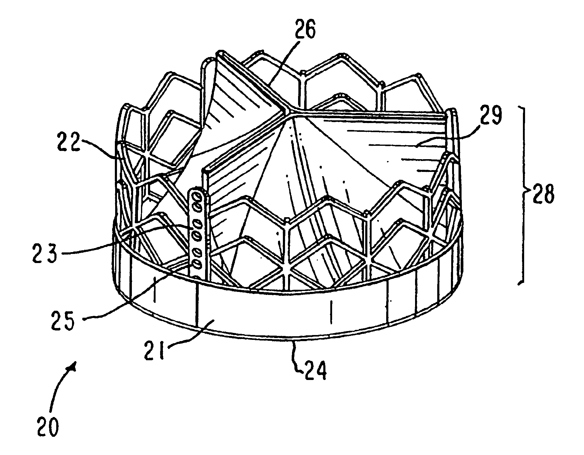
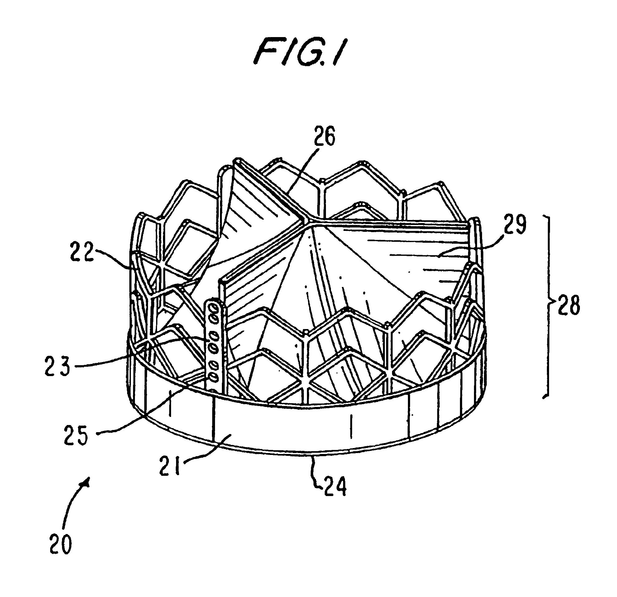
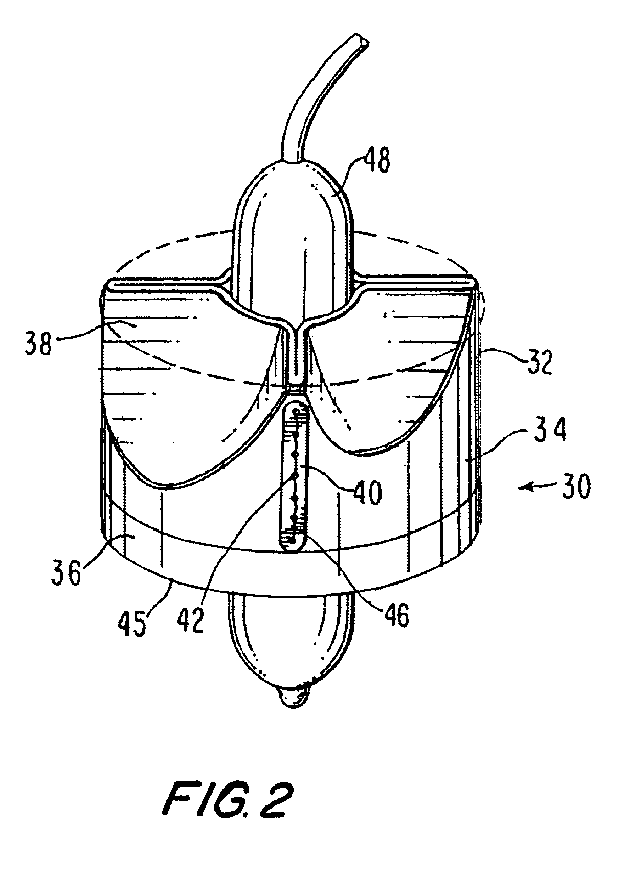
[0098]Basically the implantable prosthetic valve of the present invention comprises a leafed-valve assembly, preferably tricuspid but not limited to tricuspid valves only, consisting of a conduit having an inlet end and an outlet, made of pliant material arranged so as to present collapsible walls at the outlet. The valve assembly is mounted on a support structure such as a stent adapted to be positioned at a target location within the body duct and deploy the valve assembly by the use of deploying means, such as a balloon c...


PUM


Abstract

A valve prosthesis device is disclosed suitable for implantation in body ducts. The device comprises support stent, comprised of a deployable construction adapted to be initially crimped in a narrow configuration suitable for catheterization through the body duct to a target location and adapted to be deployed by exerting substantially radial forces from within by means of a deployment device to a deployed state in the target location, the support stent provided with a plurality of longitudinally rigid support beams of fixed length; valve assembly comprising a flexible conduit having an inlet end and an outlet, made of pliant material attached to the support beams providing collapsible slack portions of the conduit at the outlet. When flow is allowed to pass through the valve prosthesis device from the inlet to the outlet the valve assembly is kept in an open position, whereas a reverse flow is prevented as the collapsible slack portions of the valve assembly collapse inwardly providing blockage to the reverse flow.

Description

FIELD OF THE INVENTION[0001]The present invention relates to implantable devices. More particularly, it relates to a valve prosthesis for cardiac implantation or for implantation in other body ducts.BACKGROUND OF THE INVENTION[0002]There are several known prosthesis valves that have been previously described. U.S. Pat. No. 5,411,552 (Andersen et al.), entitled VALVE PROSTHESIS FOR IMPLANTATION IN THE BODY AND CATHETER FOR IMPLANTING SUCH VALVE PROSTHESIS, discloses a valve prosthesis comprising a stent made from an expandable cylinder-shaped thread structure comprising several spaced apices. The elastically collapsible valve is mounted on the stent with the commissural points of the valve secured to the projecting apices, which prevents the valve from turning inside out. Deployment of the valve can be achieved by using an inflatable balloon which in its deflated state is used to carry about it the valve structure to its position and, when inflated, deploys the stent in position to i...

Claims


Application Information

Patent Timeline
IPC IPC(8): A61F2/24A61F2/06A61F2/82
CPCA61F2/2412A61F2/2415A61F2/2418A61F2/2427A61F2/2433A61F2/2409A61F2/82A61F2230/0054A61F2220/0016A61F2250/0098A61F2220/0075A61F2220/0008A61F2002/9522A61F2210/0014A61F2220/0083A61F2230/0069A61F2250/001A61F2/9522A61F2/9524A61F2/2403A61F2/2421A61F2/243A61F2/2436A61F2/2463
Inventor SPENSER, BENJAMINBENICHU, NETANELBASH, ASSAFZAKAI, AVRAHAM
Owner EDWARDS LIFESCI PVT
Why Eureka
Try Eureka