
Deployable portable shelter

Inactive Publication Date: 2016-01-14
UNIV OF NOTRE DAME DU LAC
View PDF6 Cites 10 Cited by
  • Summary
  • Abstract
  • Description
  • Claims
  • Application Information

AI Technical Summary

Benefits of technology

The patent is about a new type of shelter that can be easily moved and set up quickly. It is made up of a rigid wall shelter that can be folded up for easy transportation. This shelter is designed to be sturdy and durable, but also portable and easy to assemble. It is made of a frame and a flexible cover that can be easily packed and shipped. The technical effects of this patent are that it provides a faster and more convenient way to set up a shelter, allowing for quicker deployment in emergency situations or for temporary use.

Problems solved by technology

As described in U.S. Pat. No. 8,602,044, tents of conventional, soft-sided construction are typically time-consuming to erect.
As described in U.S. Pat. No. 3,368,575, some shelters require additional assembly and disassembly of the framework components (with the possibility of losing parts) and may require ropes, stakes, or other auxiliary devices to maintain them in an erected condition.
WO / 2013 / 033819A1 describes large-scale collapsible fabric-covered structures, and typically the frames for such structures consist of multiple separate pieces which can become misplaced and are complicated to assemble, disassemble, and pack for shipment.
As described in U.S. Pat. No. 8,156,952, due to their temporary and portable nature, tent structures are often made of lightweight materials, which can lead to only marginally sturdy enclosures.
As described in U.S. Pat. No. 6,202,364, prefabricated structures are heavy to manipulate and often require large cranes which are expensive.
U.S. Pat. No. 6,202,364, further describes that many of the prefabricated or other type home or building structures are constructed for permanent installation and cannot be easily dismantled and reassembled on another site.
As described in U.S. Pat. No. 8,622,066, due to their design and construction at least some of these portable shelters may require a significant amount of time and labor in order to properly set the shelter up for use, and to reconfigure the portable shelter for transportation when the shelter is no longer needed.

Method used


Image

  • Deployable portable shelter
  • Deployable portable shelter
  • Deployable portable shelter

Examples


Embodiment Construction

[0025]The following disclosure of example methods and apparatus is not intended to limit the scope of the description to the precise form or forms detailed herein. Instead the following description is intended to be illustrative so that others may follow its teachings.

[0026]The shortcomings of previous efforts by others in the field of this technology may be overcome and additional advantages may be provided through a shelter having a packaged configuration and a deployed configuration. Additional features and advantages may be realized through the techniques utilized in the present shelter. Other embodiments and aspects of the shelter are described in detail herein and are considered a part of the claimed shelter. For a better understanding of the shelter with advantages and features, refer to the description and to the drawings.

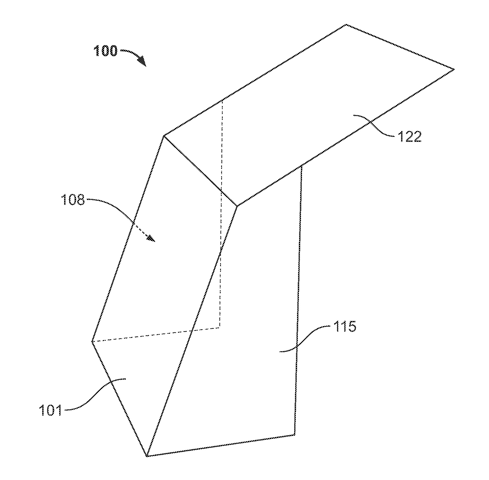
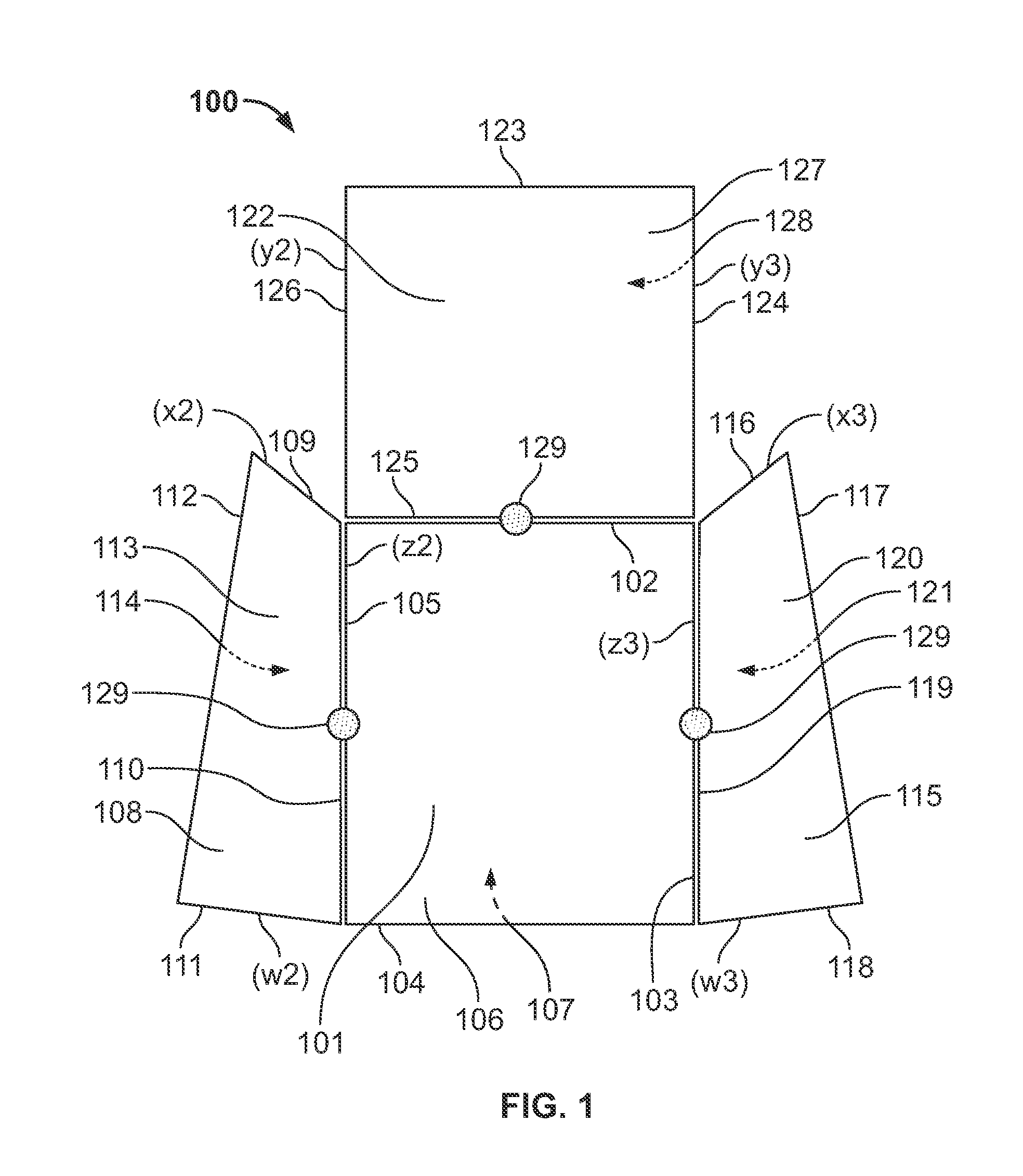
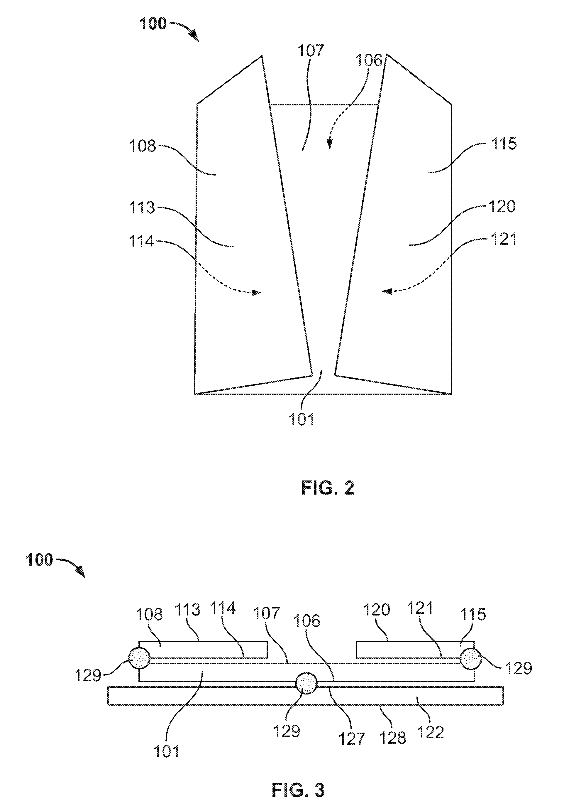
[0027]Referring to the figures, wherein like numerals indicate like or corresponding parts throughout the several views, FIG. 1 illustrates a plan view of ...


PUM


Abstract

A shelter has a packaged configuration and a deployed configuration. The shelter has four panels, each with four edges and two faces. The first and fourth panels have a rectangular shape, and the second and third panels have a quadrangle shape. The relationship of panel edge lengths and angles of the quadrangle shelter panels create a sturdy enclosure that is easy to erect, manipulate, and reconfigure. Furthermore, the shelter may be erected by rotating the panels into place via pivotal connections between the panels and optionally through the use of a lever arm.

Description

CROSS REFERENCE TO RELATED APPLICATION[0001]This application is a divisional of U.S. patent application Ser. No. 14 / 604,211, entitled “Deployable Portable Shelter,” filed Jan. 23, 2015, which claims priority to U.S. Provisional Patent Application No. 61 / 943,142, entitled “Air-Liftable, Modular, Rapidly Deployable Shelter,” filed Feb. 21, 2014, the contents and disclosure of which are each hereby incorporated by reference in their entirety.GOVERNMENT LICENSE RIGHTS[0002]This invention was made with government support under W911QY-12-C-0128 awarded by the US Army Natick Soldier Research, Development and Engineering Center (NSRDEC). The government has certain rights in the invention.FIELD OF THE DISCLOSURE[0003]The present disclosure relates generally to a rigid wall shelter having both a packaged configuration and a deployed configuration, and more particularly to a rapidly deployable portable shelter.BACKGROUND OF RELATED ART[0004]A deployable shelter transforms from a smaller packag...

Claims


Application Information

Patent Timeline
IPC IPC(8): E04B1/343E04B1/344E04H1/12
CPCE04B1/34384E04B1/34336E04B2001/34389E04B1/3445E04H1/1205E04B1/34357E04H15/008E04B1/343E04B1/34317
Inventor THRALL, ASHLEY P.DASCANIO, ANGELENE J.QUAGLIA, CHAD P.
Owner UNIV OF NOTRE DAME DU LAC
Learn More