Cooling device for multi-cylinder engine

a cooling device and engine technology, applied in the direction of engine cooling apparatus, cylinders, liquid cooling, etc., can solve the problem of high-temperature exhaust gas exposure of the cylinder head, and achieve the effect of effective acceleration of engine warming up

Active Publication Date: 2016-01-14
MAZDA MOTOR CORP
View PDF8 Cites 28 Cited by
  • Summary
  • Abstract
  • Description
  • Claims
  • Application Information

AI Technical Summary

Benefits of technology

[0005]Warming up an engine in an early stage when the engine is in a cold state is advantageous in the aspect of combustion performance and exhaust gas purification performance. In view of the above, there is a demand for a cooling device for an engine, which enables to effectively accelerate warming up of the engine when the engine is in a cold state.

Problems solved by technology

Further, a cylinder head is exposed to high-temperature exhaust gas even when the engine is in a cold state.

Method used


Image

  • Cooling device for multi-cylinder engine
  • Cooling device for multi-cylinder engine
  • Cooling device for multi-cylinder engine

Examples


Embodiment Construction

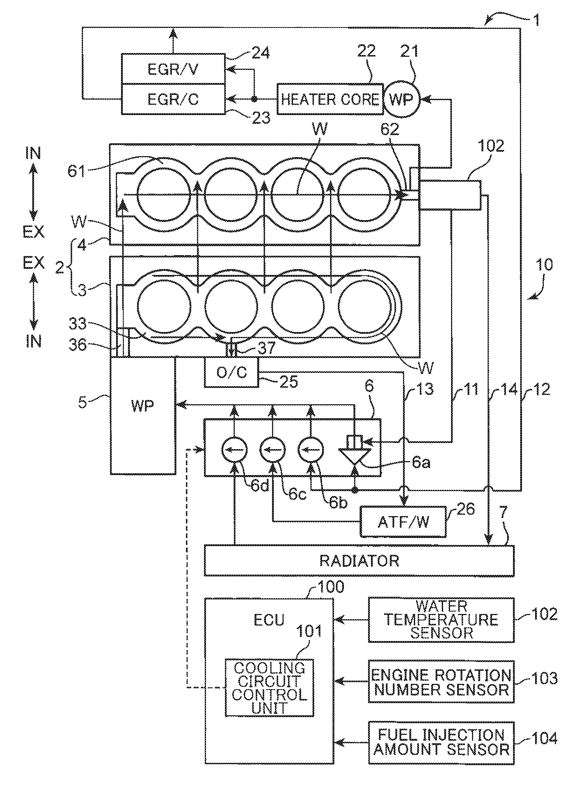
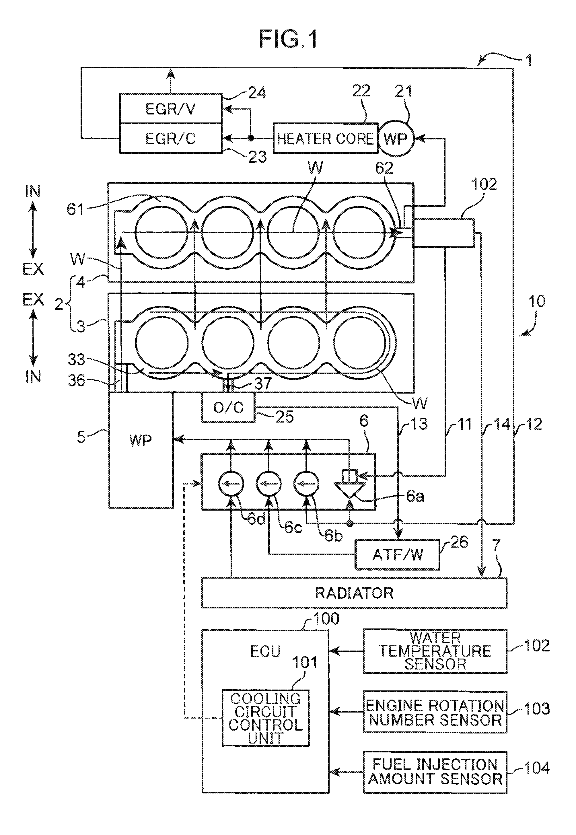
[0027]In the following, an embodiment of a cooling device for a multi-cylinder engine according to the invention is described referring to FIG. 1 to FIG. 15D.

[0028]FIG. 1 is a diagram illustrating a schematic configuration of a cooling device 1 for a multi-cylinder engine 2 in an embodiment of the invention. The multi-cylinder engine 2 (hereinafter, simply called as an “engine”) is a so-called cross flow type in-line 4-cylinder diesel engine, in which four cylinders are disposed in series in an unillustrated crankshaft direction (left and right directions in FIG. 1), and an intake system and an exhaust system are disposed opposite to each other with respect to a cylinder head 4. The engine 2 is loaded in an engine room (not illustrated) provided at a vehicle front portion in such a manner that an array of cylinders is aligned in the vehicle width direction, the exhaust system is located on the rear side in the vehicle front and rear directions, and a cylinder axis of each cylinder e...


PUM


Abstract

A cylinder block (3) includes an inlet portion (36), a narrow portion (42), and an inclined portion (43). A cylinder head includes a head-side discharge portion. The inlet portion is formed on the first cylinder side of a cylinder array, and introduces coolant to a block-side water jacket (33). The narrow portion is formed in the vicinity of the inlet portion, and restricts the coolant introduced through the inlet portion from flowing to an intake-side channel (35) of the block-side water jacket. The inclined portion is formed in the vicinity of the inlet portion, and guides the coolant introduced through the inlet portion toward the head. The head-side discharge portion is formed on the fourth cylinder side of the cylinder array, and discharges the coolant from a head-side water jacket. A communication path for communicating between the water jackets is formed on the head side of the inclined portion.

Description

TECHNICAL FIELD[0001]The present invention relates to a cooling device for a multi-cylinder engine of an automobile or a like vehicle, and more particularly, to a technical field of engines configured to cool a cylinder head and a cylinder block by coolant.BACKGROUND ART[0002]Conventionally, in an automobile or a like vehicle, there is provided a cooling device configured to cool an engine by flowing coolant to an inside of the engine so as to obtain an appropriate temperature of the engine.[0003]For instance, Patent Literature 1 discloses a technique, in which a spacer is disposed in a water jacket of a cylinder block. A guide slope portion for guiding coolant toward the cylinder head portion is formed on the coolant inlet portion of the spacer. A channel separation member constituting an upper channel of the water jacket continues to the upper end of the guide slope portion. According to this configuration, increasing the flow rate and the flow speed of coolant flowing through the...

Claims


Application Information

Patent Timeline
Patent Type & Authority Applications(United States)
IPC IPC(8): F01P3/02F01P5/10F01P7/16
CPCF01P3/02F01P7/16F01P5/10F01P2003/028F01P2060/16F02F1/14
Inventor MATSUMOTO, DAISUKETABATA, DAISUKENAITO, MASAHIRO
Owner MAZDA MOTOR CORP
Why Eureka
Try Eureka