Safety and identification system for garments

a technology of identification system and garment, applied in the field of high-visibility apparel, can solve the problems of increasing the risk of collision between motor unacceptably unacceptable high risk of collision between vehicles and non-motor vehicles, so as to improve visibility

Inactive Publication Date: 2016-01-21
FONTE CHRISTOPHER
View PDF4 Cites 10 Cited by
  • Summary
  • Abstract
  • Description
  • Claims
  • Application Information

AI Technical Summary

Benefits of technology

[0006]In some embodiments, the high-visibility face further includes a third light emitter that identifies the wearer. In some embodiments, the third light emitter includes a triangular LED cluster. In some embodiments, the third light emitter includes a line of LEDs. In some embodiments, the light emitters include LEDs. In some embodiments, the light emitters include LED clusters. In some embodiments, the third light emitter is on an abdominal portion of the high visibility face. In some embodiments, the first and second light emitters include triangular LED clusters. In some embodiments, the light emitters include LED ribbons. In some embodiments, the first and second light emitters are at the widest points of the shoulders of the high-visibility face. In some embodiments, both the front and back faces of the garment are high-visibility faces.

Problems solved by technology

Modern roadways are primarily designed for motor vehicle use, and the risk of collisions between vehicles and non-motor vehicle operators as well as low visibility vehicles (such as motorcycles) is unacceptably high.
Motorists' primary attention on other motor vehicles on the road, the poor visibility of smaller motorized and non-motorized objects, and the discrepancy in speed between motor vehicles and non-motor vehicles are also factors that increase the risk of these collisions.
As fuel costs and interest in physical fitness have increased, the number of bicyclists and pedestrians on roadways has also increased.
This has increased the potential for collisions.
These collisions are devastating for the pedestrian / bicyclist / motorcyclist and road workers because they are completely exposed and unprotected.
However, these systems typically rely on single points of steady or flashing lights (or reflections) that may appear random or arbitrary to motorists traveling at speed.
It is difficult for motorists to discern the difference and origin of the various forms of reflections and emitted lights on the roadway.
Therefore, motorists' ability to determine the speed, distance, size, and identity of the cyclist / pedestrian / worker employing these systems is extremely limited.

Method used


Image

  • Safety and identification system for garments
  • Safety and identification system for garments
  • Safety and identification system for garments

Examples


Embodiment Construction

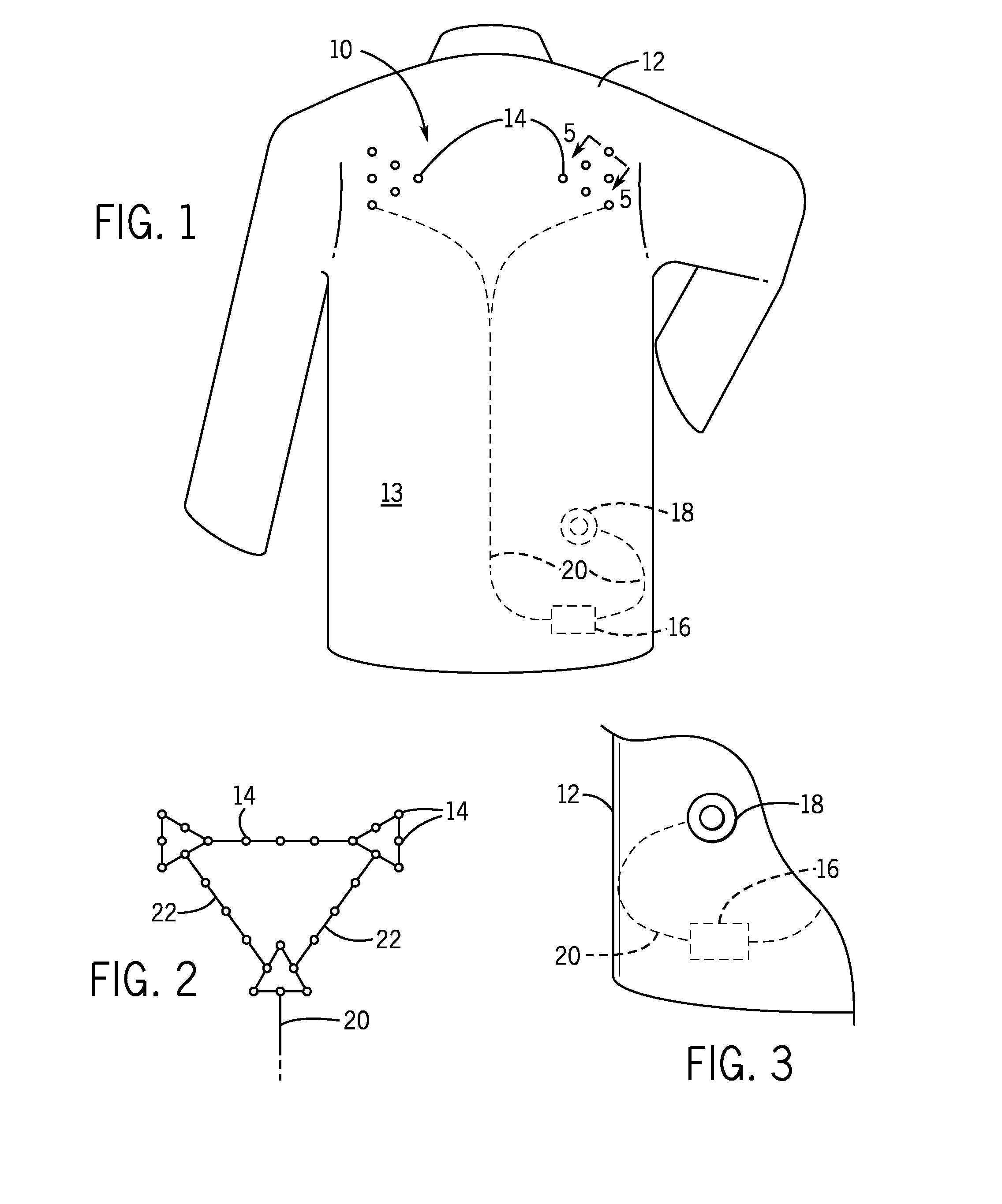
[0015]FIG. 1 is a partially transparent view of the back of a high visibility garment 12 according to one embodiment. Garment 12 (a jacket in this embodiment) comprises material 13 and visibility system 10. In this embodiment, visibility system 10 comprises LEDs 14, switch 18, a power source 16, and electrical connections 20.

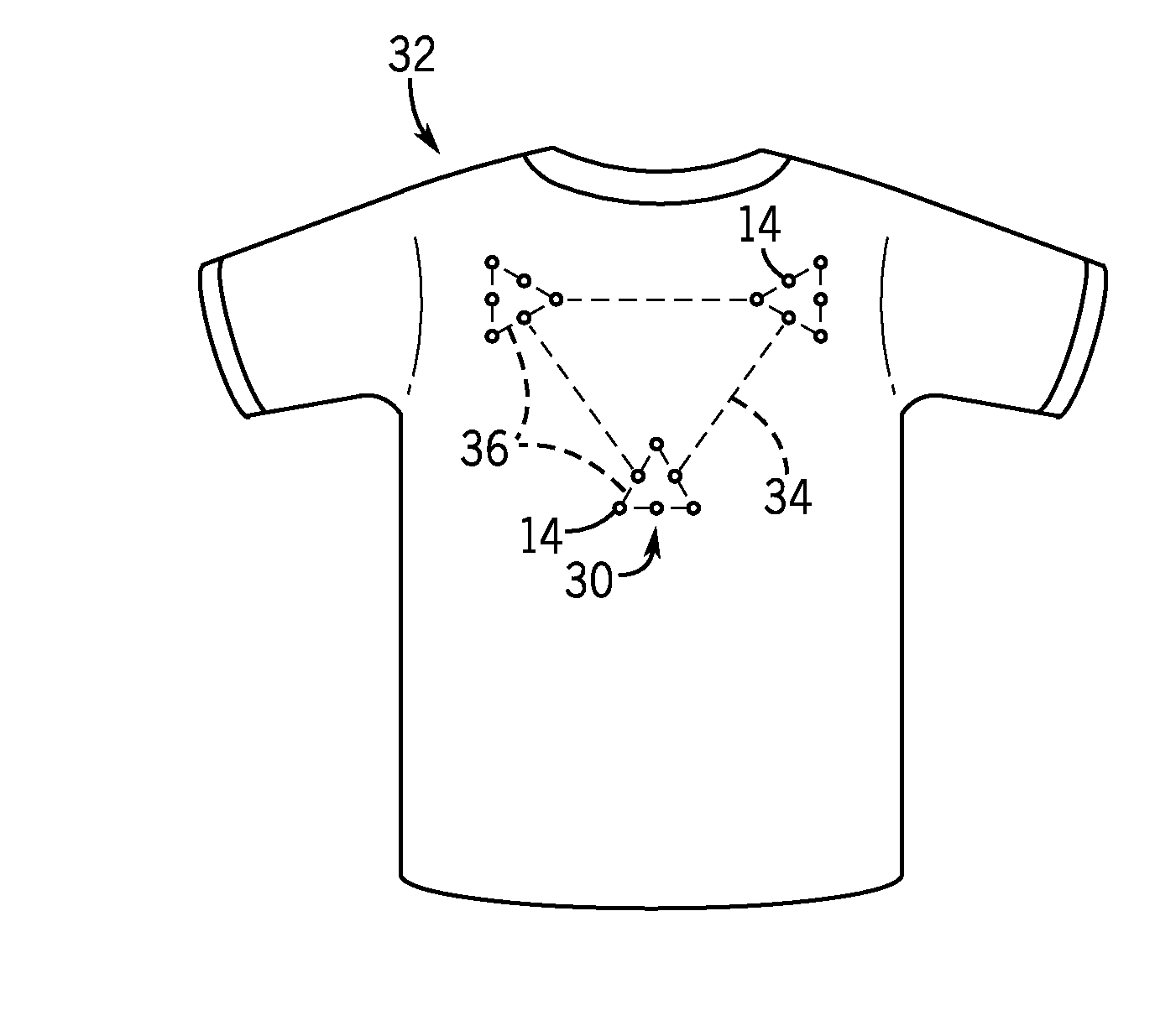
[0016]In the embodiments shown in FIGS. 2 and 7, LEDs 14 are arranged in three triangular clusters. The first and second clusters are located at the widest points of the shoulders, to maximize their distance from each other and their height on garment 12. The first and second light clusters are highly visible in order to quickly grab the attention of passing motorists. The two shoulder clusters will appear to diverge as a motorist approaches garment 12, and will appear to converge as the motorist moves away from garment 12. This optical effect allows the motorist to quickly assess the relative speed, direction, and distance of the wearer. Such information is not...


PUM


Abstract

An upper body garment with improved visibility includes a high-visibility face that is one of the front or back faces of the garment. The high-visibility face includes a first light emitter on a right shoulder portion and a second light emitter on a left shoulder portion. The high-visibility face further includes a first light emitter pattern formed by the first and second light emitters that grabs attention and visibly diverges when approached. The high-visibility face further includes a third light emitter that identifies the wearer.

Description

TECHNICAL FIELD[0001]The system described herein generally relates to the field of apparel. More specifically, the system relates to high visibility apparel.BACKGROUND[0002]High-visibility clothing has applications in a number of fields, including air travel, construction, hunting, and on roadways. Modern roadways are primarily designed for motor vehicle use, and the risk of collisions between vehicles and non-motor vehicle operators as well as low visibility vehicles (such as motorcycles) is unacceptably high. Motorists' primary attention on other motor vehicles on the road, the poor visibility of smaller motorized and non-motorized objects, and the discrepancy in speed between motor vehicles and non-motor vehicles are also factors that increase the risk of these collisions. As fuel costs and interest in physical fitness have increased, the number of bicyclists and pedestrians on roadways has also increased. This has increased the potential for collisions. These collisions are deva...

Claims


Application Information

Patent Timeline
Patent Type & Authority Applications(United States)
IPC IPC(8): F21V33/00A41D27/08
CPCA41D27/085F21V33/0008F21W2111/10F21Y2103/003F21Y2101/02A41D1/002A41D13/01G08B5/004F21Y2103/10F21Y2115/10
Inventor FONTE, CHRISTOPHER
Owner FONTE CHRISTOPHER
Why Eureka
Try Eureka