
Curvilinear Transosseous Rotator Cuff Repair Tools

a rotator cuff and transosseous technology, applied in the field of surgical methods and surgical tools, can solve the problems of surgeons not meeting their need to know where the medial tunnel is created when the tool is operated, surgeons cannot plan where the medial tunnel is created, and the surgeon's need to know where the tool is operated was not met, so as to achieve more control over the bone bridge

Inactive Publication Date: 2016-01-21
MICROAIRE SURGICAL INSTR
View PDF8 Cites 18 Cited by
  • Summary
  • Abstract
  • Description
  • Claims
  • Application Information

AI Technical Summary

Benefits of technology

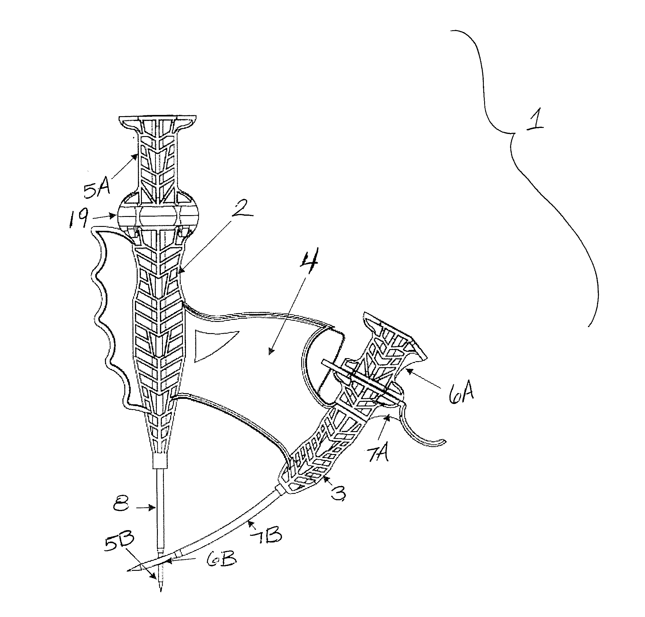
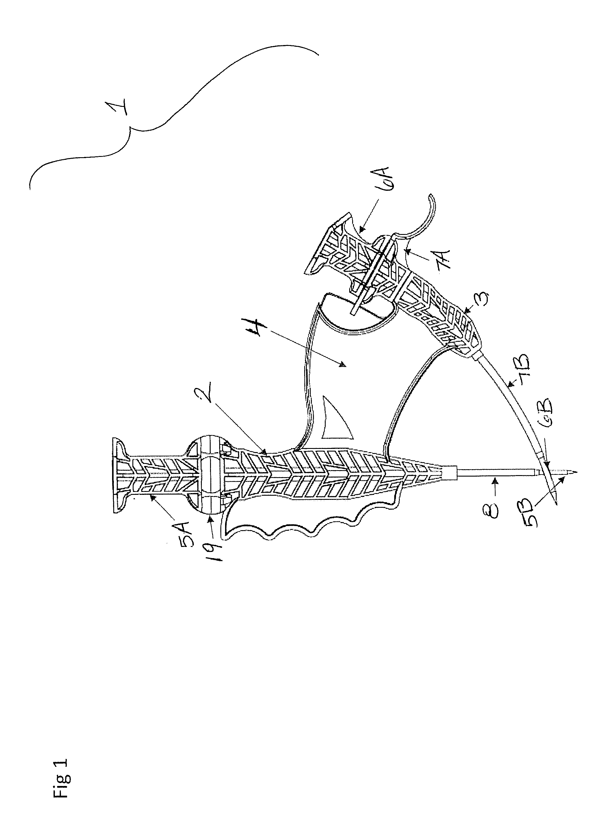
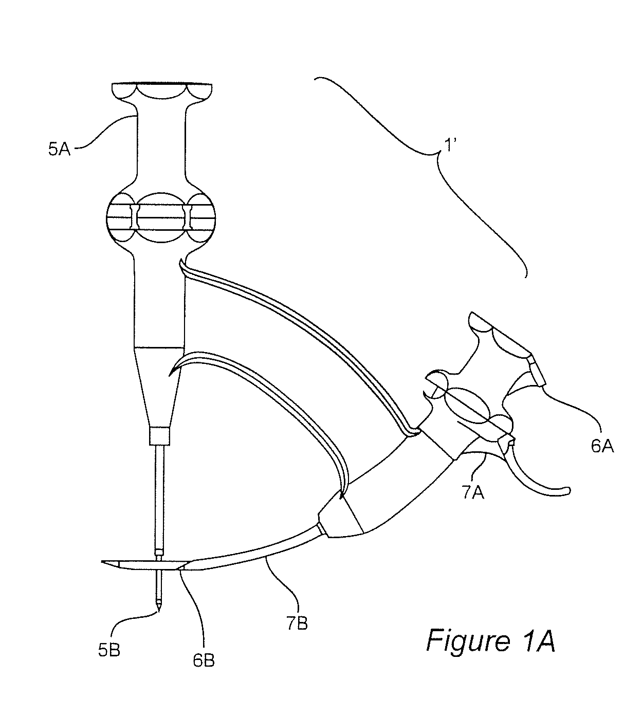
The patent is about surgical tools, devices, and methods that are particularly useful for rotator cuff surgery. These tools help the surgeon perform the surgery without needing large incisions and provide them with more control over where the tunnels are formed in the bone. This results in a more targeted and precise surgical experience for the patient.

Problems solved by technology

For example, one problem with much existing technology used in conventional rotator cuff surgery is that typically at least one relatively-big dermal incision must be made in the shoulder.
Another shortcoming of existing surgical tools is that a surgeon's need to know where a tunnel is created when the tool is operated was not being met, for example, the surgeon had to tolerate the medial tunnel appearing wherever the tool created the tunnel and the surgeon was unable to plan where the medial tunnel would be created.
Another problem with existing tools used for rotator cuff surgery is that the surgeon is not given a range of options for where the second tunnel can be formed in the bone and correspondingly, when the conventional tools are used and the second tunnel is formed, a bone bridge that results is not necessarily of desirable dimensions or geometry, and often is a thinner bone bridge than would be desirable.

Method used


Image

  • Curvilinear Transosseous Rotator Cuff Repair Tools
  • Curvilinear Transosseous Rotator Cuff Repair Tools
  • Curvilinear Transosseous Rotator Cuff Repair Tools

Examples


example 1

[0130]A syringe 10 is attached to an inventive tool at handle 2′ (FIG. 2) at harvest port 9. Syringe 10 is attachable and detachable from handle 2′.

example 2

[0131]In this inventive example, a guide kit comprises a guide body 11 and straight cannula; straight obturator; curved cannula; curved obturator; and suture retriever 15.

example 3

[0132]In this inventive example, a Curvilinear Transosseous Rotator System simplifies and improves arthroscopic transosseous repair and saves time, provides rigid fixation, and provides multiple suturing options. Percutaneous streamlined tunneling is provided, which saves time and reduces incisions to small punctures. Transtendon UHMPE sutures are placed without needing secondary suturing devices. Bone bridges formed by the system of this example are robust. Extending past the Greater Tuberosity, tunnels are at maximum proportions to the patient. Suturing uses preloaded Transtendon Passing Loops for rapid Transtendon constructs. Inventive subcortical knots reduce stress concentration points and provide low profile fixation. Surgeons who wish to harvest humeral head bone marrow aspirate (BMA), can do so using the inventive system. BMA is capable of being drawn through a port during tunneling—avoiding need of a BMA Harvest Kit, associated surgical time and secondary operative sites.

FU...


PUM


Abstract

Rotator cuff tears (complete and partial) are surgically repaired without needing more dermal access than percutaneous punctures. The surgeon is afforded a range of options for where to place a second tunnel in the bone, and selection by the surgeon of a desired bone bridge size is provided in advance of tunnel construction. Also, stitching in rotator cuff surgery can be accomplished without the need for suture anchors or added cost of secondary suture passers. Multiple stitch configurations including X-patterns are possible with combinations of preloaded loops and or sutures passed simultaneously through tissue and bone. Fixation is achieved without the use of suture anchors, buttons or other rigid implants.

Description

FIELD OF THE INVENTION[0001]The invention relates to surgical methods and surgical tools, especially for rotator cuff surgery.BACKGROUND OF THE INVENTION[0002]In connection with surgery for rotator cuff repair, certain surgical tools and technology are known. The patent literature includes certain work regarding rotatory cuff surgery, mentioned in roughly chronological order as follows:[0003]U.S. Pat. No. 6,514,274 issued Feb. 4, 2003 to Boucher et al. (Arthrotek, Inc.), for “Method and apparatus for rotator cuff repair.”[0004]U.S. Pat. No. 7,569,059 issued Aug. 4, 2009 to Cerundolo (Arthroscopic Innovations LLC) for “Method and apparatus for surgical repair.”[0005]U.S. Pat. No. 7,604,659 issued Oct. 20, 2009 to Lee, for “Method and apparatus for repair of torn rotator cuff tendons.”[0006]U.S. Pat. No. 7,771,441 issued Aug. 10, 2010 to Cerundolo for “Method and apparatus for providing suture in a passageway.”[0007]U.S. Pat. No. 7,833,230 issued Nov. 16, 2010 to Cerundolo for “Method...

Claims


Application Information

Patent Timeline
Patent Type & Authority Applications(United States)
IPC IPC(8): A61B17/04
CPCA61B17/0469A61B2017/0477A61B2017/0472A61B17/0482A61B17/0485A61B2017/06019A61B2017/06095A61B2090/034A61B2090/0807A61B17/1604A61B17/1642A61B17/16
Inventor KELLER, DOUGLASVANLEEUWEN, RYANDROSS, BRIAN D.
Owner MICROAIRE SURGICAL INSTR
Learn More