
Circuit breakers with handle bearing sleeves

a technology of handle bearing sleeves and circuit breakers, which is applied in the direction of circuit breakers, circuit breakers for excess current, and protection switches for excess current, etc., and can solve problems such as b> wear into the handle, handle undetected deformation, and circuit breakers

Active Publication Date: 2016-02-18
EATON INTELLIGENT POWER LTD
View PDF5 Cites 13 Cited by
  • Summary
  • Abstract
  • Description
  • Claims
  • Application Information

AI Technical Summary

Benefits of technology

The patent text describes a handle bearing configuration that can withstand the UL489 endurance test requirements for 10,000 repetitions of handle movement through the operative positions without failure or degradation. This means that the handle bearing configuration is designed to be durable and reliable, and can be used repeatedly without causing any problems.

Problems solved by technology

Because the movable contact is fixedly attached to the rotating arm, the arm pivots and physically separates the stationary and movable contacts, thus tripping the circuit.
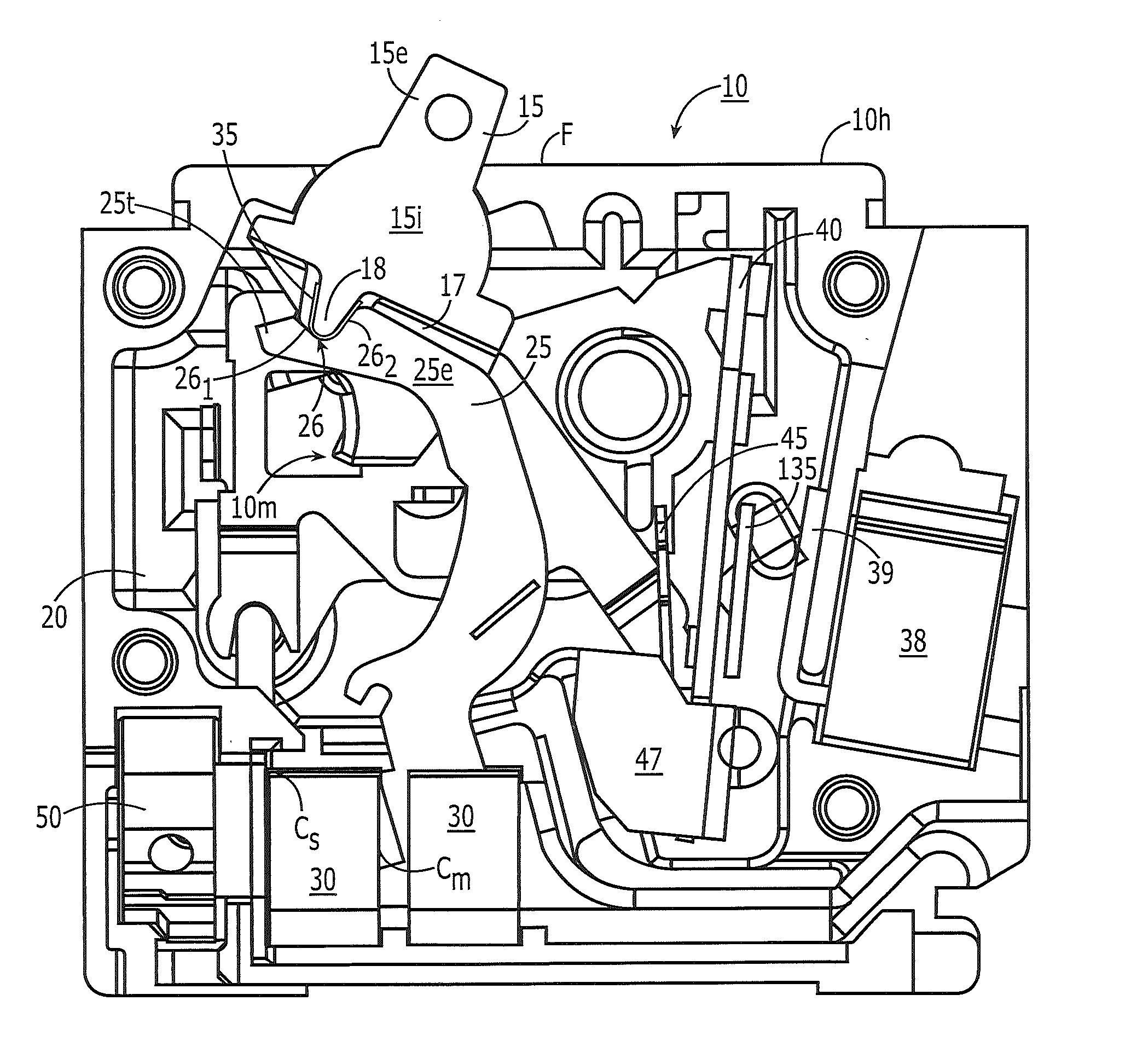
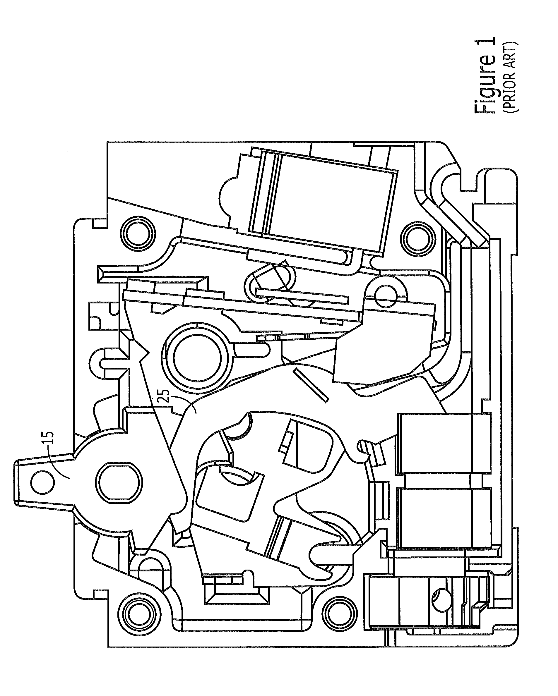
The moving arm 25 may wear into the handle or the handle may undesirably degrade, e.g., exhibit blistering due to one or more of heat, friction and / or forces from the arm.

Method used


Image

  • Circuit breakers with handle bearing sleeves
  • Circuit breakers with handle bearing sleeves
  • Circuit breakers with handle bearing sleeves

Examples


Embodiment Construction

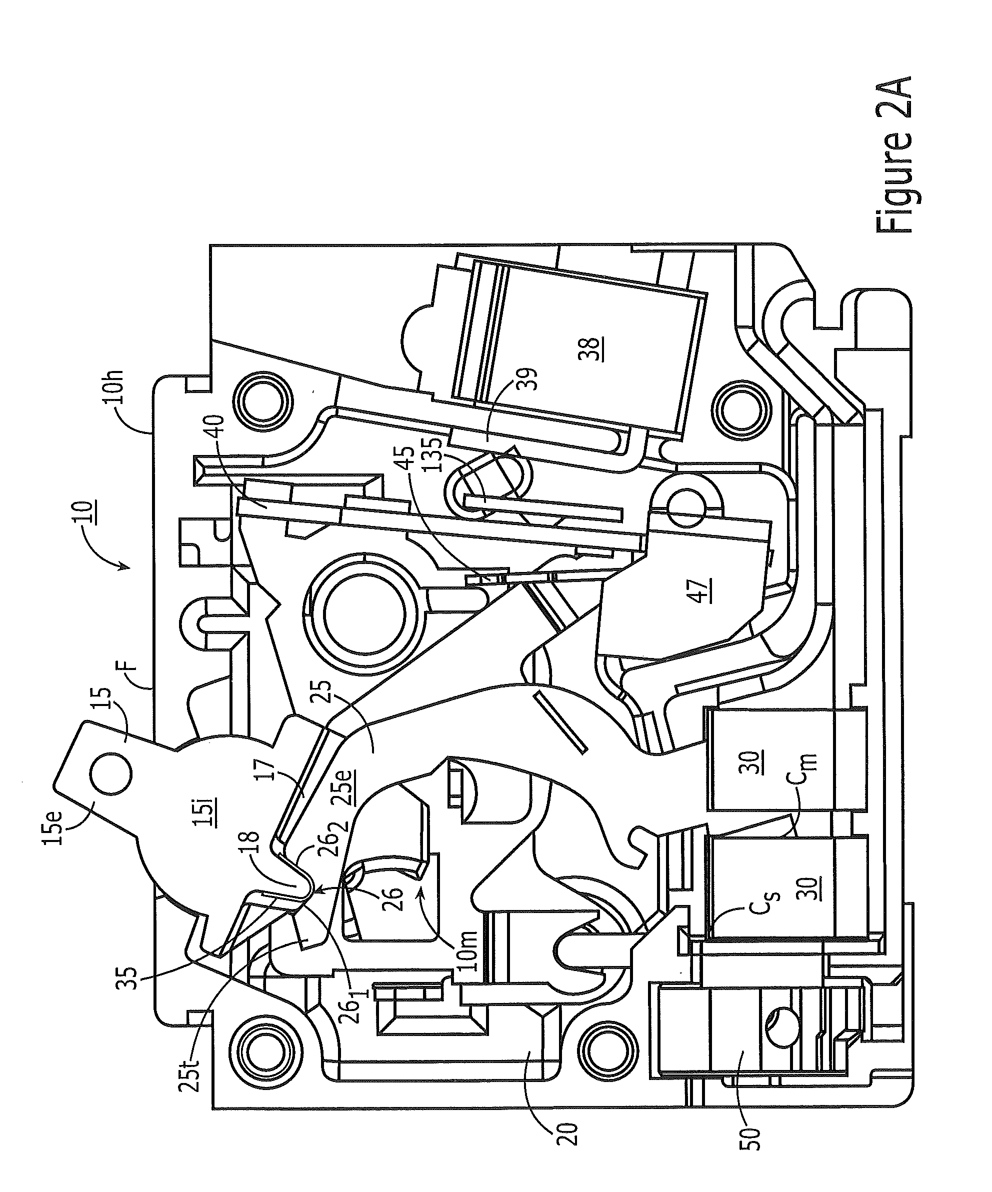
[0005]Embodiments of the present invention are directed to circuit breakers with new and inventive handle bearing configurations.

[0006]Embodiments of the invention are directed to circuit breakers with a housing and a pivotable handle held by the housing. The handle has a handle bearing segment, typically configured as an inwardly extending protrusion. The circuit breaker also has an arm held in the housing in communication with the handle, the arm having opposing first and second end portions. The first end portion of the arm is held in an arm receiving channel in the handle and the second end portion has an electrical movable contact. The circuit breaker also has a stationary electrical contact held in the housing so as to selectively electrically engage the movable contact. The circuit breaker also has a sleeve held on the handle bearing segment, typically the protrusion, so that the first end portion of the arm moves against the sleeve as the arm and handle move between ON and O...


PUM


Abstract

Circuit breakers with handles having a handle bearing sleeve that contacts an upper end portion of a moving arm and allows the arm to rotate to “OFF”, “ON” and “TRIP” positions, typically with about 90 degrees of rotation.

Description

FIELD OF THE INVENTION[0001]The present invention relates to circuit breakers.BACKGROUND OF THE INVENTION[0002]Circuit breakers are one of a variety of overcurrent protection devices used for circuit protection and isolation. The circuit breaker provides electrical protection whenever an electric abnormality occurs. In a typical circuit breaker, current enters the system from a power line and passes through a line conductor to a stationary contact fixed on the line conductor, then to a movable contact. The movable contact is fixedly attached to a pivoting arm. As long as the stationary and movable contacts are in physical contact, current passes from the stationary contact to the movable contact and out of the circuit breaker to down-line electrical devices.[0003]In the event of an overcurrent condition (e.g., a short circuit), extremely high electromagnetic forces can be generated. The electromagnetic forces repel the movable contact away from the stationary contact. Because the mo...

Claims


Application Information

Patent Timeline
Patent Type & Authority Applications(United States)
IPC IPC(8): H01H71/02H01H71/24
CPCH01H71/025H01H2205/002H01H71/24H01H71/521H01H71/522
Inventor MALONEY, JAMES GERARDGATES, DANIEL QUENTIN
Owner EATON INTELLIGENT POWER LTD
Learn More