Rolling Shutter Synchronization

a rolling shutter and synchronization technology, applied in the field of camera systems, can solve the problems of difficult use, difficult to use, and large bulky 3d photography equipment, and advanced multi-lens cameras that are not affordable to amateur photographers or moviemakers, and require considerable experience, effort and time for manipulation of images

Active Publication Date: 2016-02-18
GOPRO
View PDF8 Cites 48 Cited by
  • Summary
  • Abstract
  • Description
  • Claims
  • Application Information

AI Technical Summary

Problems solved by technology

Traditionally, 3D photography requires expensive stereoscopic cameras that are often bulky and difficult to use.
Similarly, panoramic photography in two-dimensional (2D) and 3D traditionally requires advanced multi-lens cameras that are not affordable to the amateur photographer or moviemaker.
However, capturing the sequence of images correctly and the subsequent manipulation of the images requires considerable experience, effort and time—in addition to expensive software—which prevents the majority of amateur photographers from being able to generate such images at all.
Furthermore, the capturing methods described above, while acceptable for generating images of static environments with stationary cameras, are not only unwieldy but unacceptable solutions for action shots (moving camera or object), let alone video recordings.

Method used


Image

  • Rolling Shutter Synchronization
  • Rolling Shutter Synchronization
  • Rolling Shutter Synchronization

Examples


example embodiments

Overview of Example Embodiments

[0029]Example embodiments detailed herein relate to a multi-camera system with opposing and / or converging rolling shutters (RSs) for mitigating overlapping field of view (FOV) artifacts resulting from camera or object motion during RS image / video frame capture. In order to mitigate FOV artifacts, the multi-camera system includes cameras configured such that a selection of any two adjacent cameras features opposing or converging RSs. The opposing and converging RSs capture image data at the cameras' overlapping FOV at temporally proximate times, thus preventing or significantly reducing time-delay artifacts.

[0030]In one example embodiment, the multi-camera system with opposing and / or converging RSs includes a first complementary metal oxide semiconductor (CMOS) image sensor adjacent to a second CMOS image sensor. The first CMOS is associated with a first RS configured to roll in a first direction relative to an orientation of the first CMOS. The second ...

example field

of View Artifacts

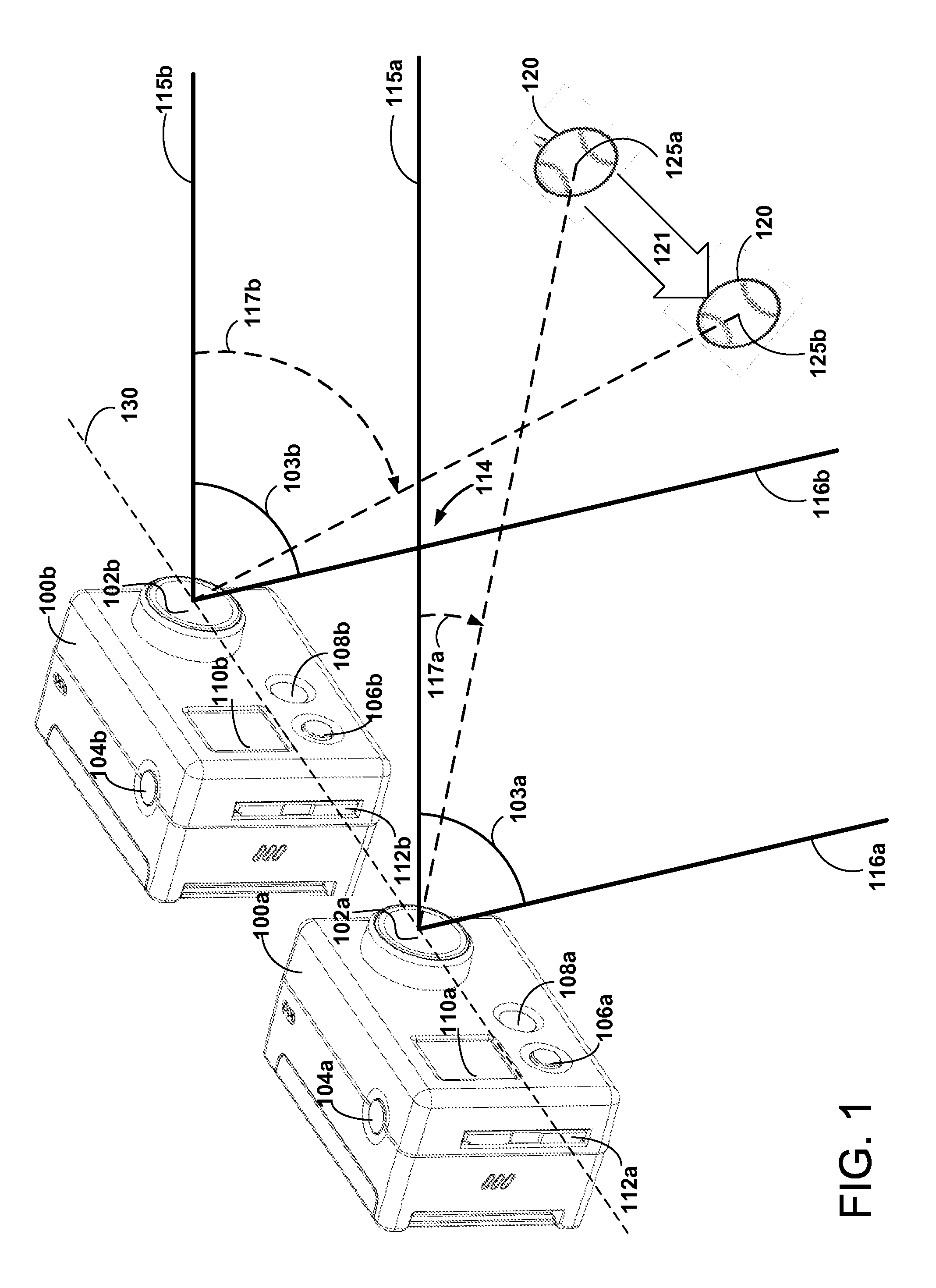
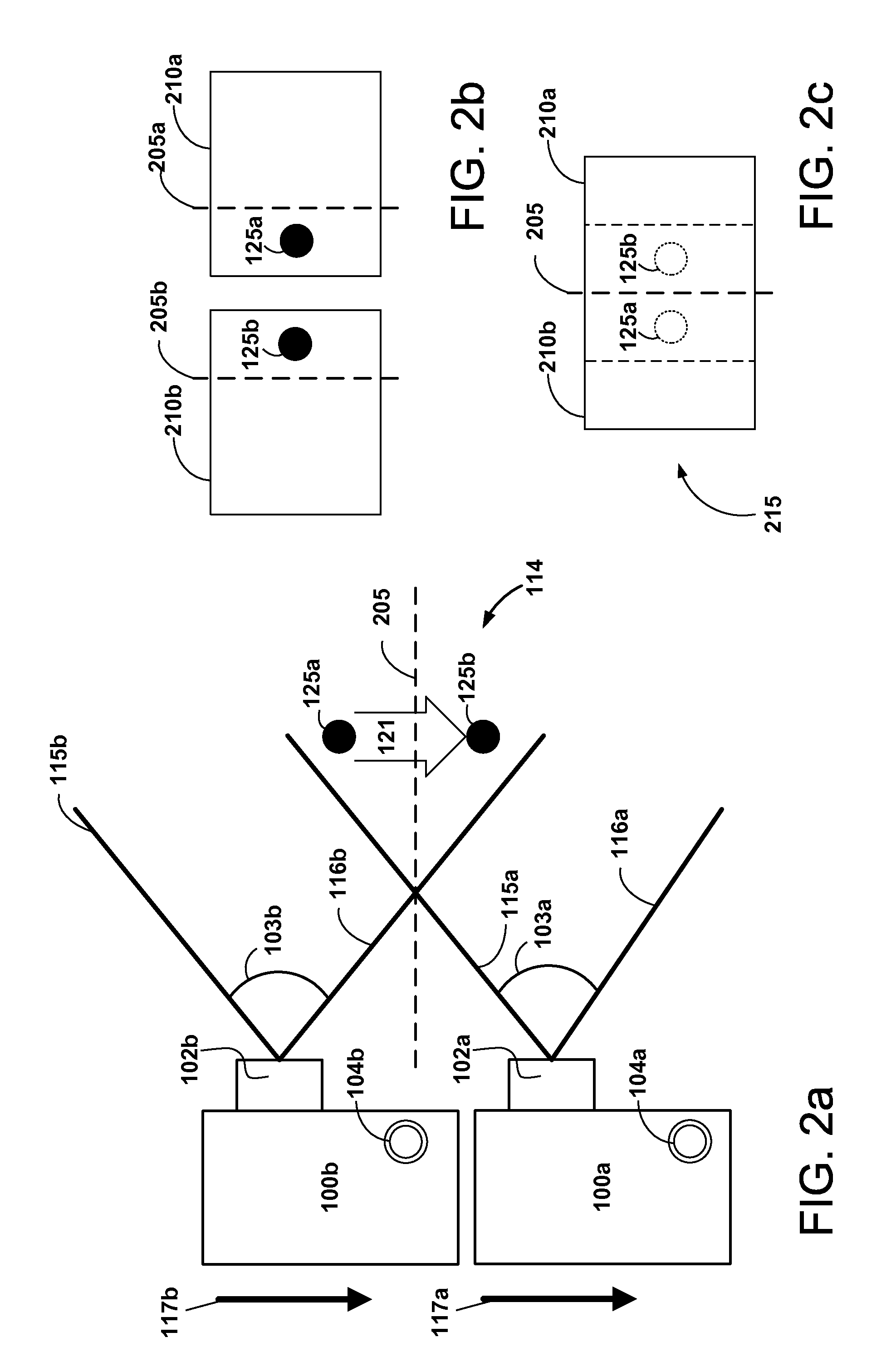
[0041]FIG. 1 is a diagram illustrating an example FOV artifact due to overlapping field of views of two adjacent cameras according to one example embodiment. In some example embodiments, the adjacent cameras 100a and 100b belong to different, but adjacent, 3D camera pairs (paired cameras omitted) which are each configured for capturing synchronized 3D image data. The 3D image data from the camera pairs is stitched together to form 3D panoramic images or video. In other example embodiments, the adjacent cameras 100a and 100b are each configured for capturing synchronized 2D image data which is stitched together to form 2D panoramic images or video.

[0042]As shown, each camera 100a, 100b includes a lens 102, a shutter button 104, a function button 106, an indicator light 108, a control display screen 110, and a memory card slot 112. Other conventional camera features not specifically illustrated or described may also be included in camera 100a or camera 100b. For examp...

example camera

Configurations for Mitigating FOV Artifacts

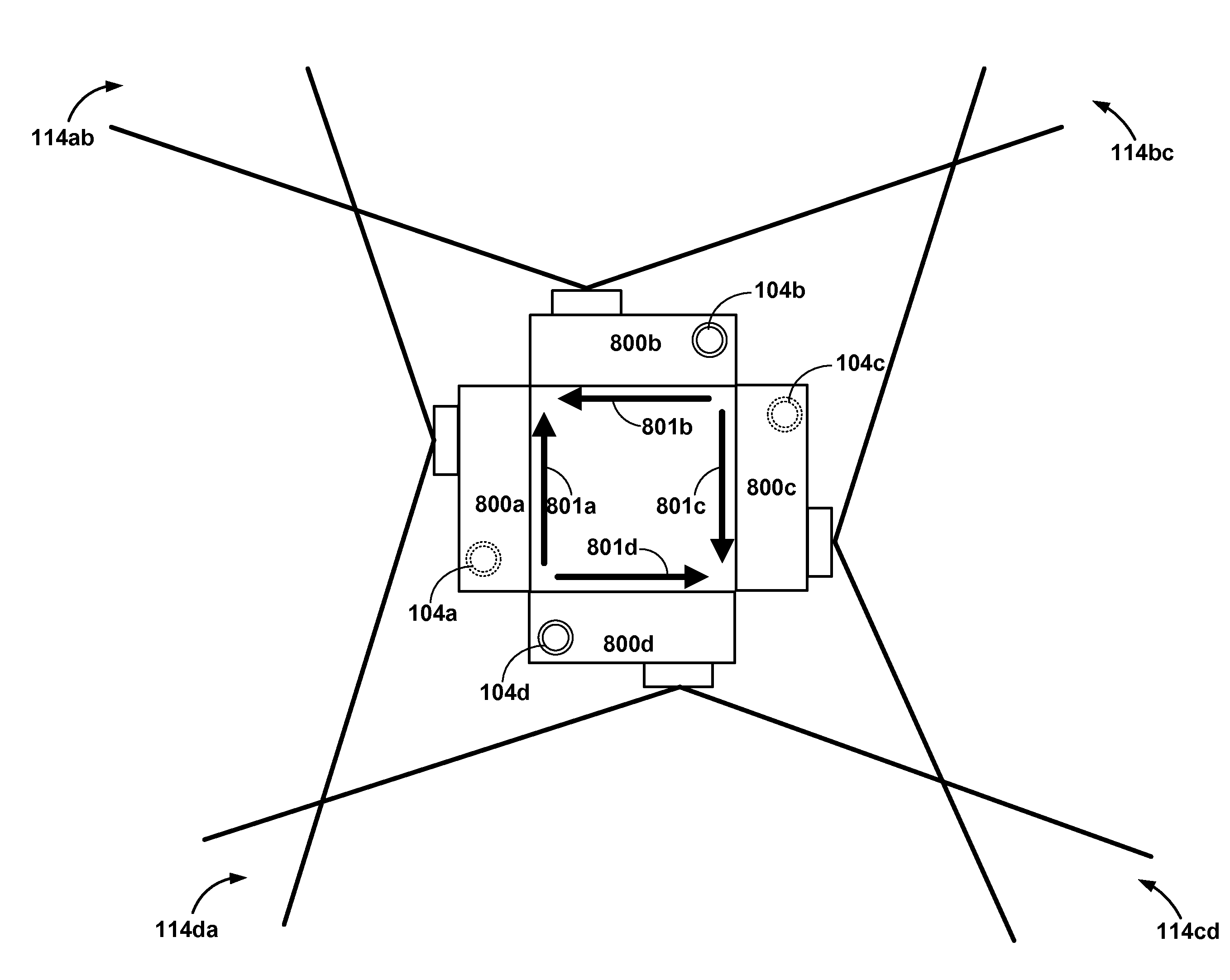
[0063]FIGS. 4 through 8 illustrate example embodiments of a camera system for mitigating FOV artifacts. The cameras and camera systems discussed with reference to those figures may include configurable RSs. Alternatively, one or more cameras may include an RS configured to roll in a direction different than that of another camera. Furthermore, example embodiments include systems of two or more cameras with the same RS direction but different camera orientations for changing—relative to another camera—the RS directions of the camera system.

[0064]Additionally, one or more of the illustrated example embodiments includes a camera housing for orienting (e.g., to change the RS direction or position the camera) or protecting one or more cameras. The housing may be, for example, a clear rigid housing structured to secure two or more cameras. The housing may be structured such that the FOV overlap region between two adjacent cameras whose image data...


PUM


Abstract

A camera system configuration generates 2D or 3D images capable of being stitched together to create panoramic images. The configuration detects a communication coupling of at least two cameras for capturing a sequence of images. The cameras themselves are configured such that their rolling shutters mitigate field of view artifacts from adjacent cameras (2D panoramas) and adjacent 3D camera pairs (3D panoramas) by allowing for the substantially temporally-aligned capture of light in overlap regions between adjacent cameras.

Description

CROSS REFERENCE TO RELATED APPLICATIONS[0001]This application is a continuation of U.S. application Ser. No. 13 / 610,753, filed Sep. 11, 2012, now U.S. patent Ser. No. ______, which application claims the benefit of Provisional Application No. 61 / 667,882, filed on Jul. 3, 2012, all of which are incorporated by reference in their entirety.BACKGROUND[0002]1. Technical Field[0003]This disclosure relates to a camera system, and more specifically, to a configurable camera system, for capturing 2D and 3D panoramic images or video, that mitigates field of view artifacts.[0004]2. Description of the Related Arts[0005]In recent years, amateur use of digital cameras has increased dramatically as improvements in digital camera technology have allowed cameras to become more affordable and user-friendly. However, advanced forms of digital photography such as panoramic and three-dimensional (3D) panoramic imaging have conventionally been available only to professional photographers and filmmakers. ...

Claims


Application Information

Patent Timeline
Patent Type & Authority Applications(United States)
IPC IPC(8): H04N5/232H04N5/262H04N5/247H04N13/02G03B9/28G03B7/00H04N13/239
CPCG08B13/19641G02B27/2264H04N13/0296H04N13/0425H04N13/0055H04N13/0497H04N5/3415H04N5/2254G06T2207/10021G06K2009/2045G02B27/2228H04N13/0051G03B35/08G03B37/04G03B9/08H04N5/2258H04N5/3532H04N13/0242H04N5/23238H04N5/2252H04N13/0246G03B7/00G03B9/28H04N5/2628H04N5/247H04N13/0239G08B13/19628H04N13/239H04N13/243H04N13/296G02B30/24H04N23/60H04N23/698H04N25/531H04N23/90H04N13/167H04N13/189H04N13/246H04N13/327H04N13/398G02B30/34H04N23/45H04N23/51H04N25/41
Inventor CAMPBELL, SCOTT PATRICK
Owner GOPRO
Why Eureka
Try Eureka