Power Lock System for Stage Truss Towers

Active Publication Date: 2016-03-03
DARDEN BRUCE WILLIAM
View PDF0 Cites 11 Cited by
  • Summary
  • Abstract
  • Description
  • Claims
  • Application Information

AI Technical Summary

Benefits of technology

The patent describes a Power Lock System for Stage Truss Towers. The system ensures that the load is secured when locked off, and it also provides remote feedback that the forks are fully retracted and vertical travel is possible. The technical effects of this system include improved safety and efficiency in stage construction.

Problems solved by technology

The uplift occurs predominately when gusts of winds or fast approaching storms with sustained wind do not allow the roof structure to be lowered.
The impact is severe enough to rupture the aluminum structure, deform hooks, or disconnect the end of the strap previously held in tension.
Seismic loads challenge the connection between the sleeve and truss by changing the relative location of the tower base.

Method used


Image

  • Power Lock System for Stage Truss Towers
  • Power Lock System for Stage Truss Towers
  • Power Lock System for Stage Truss Towers

Examples


Embodiment Construction

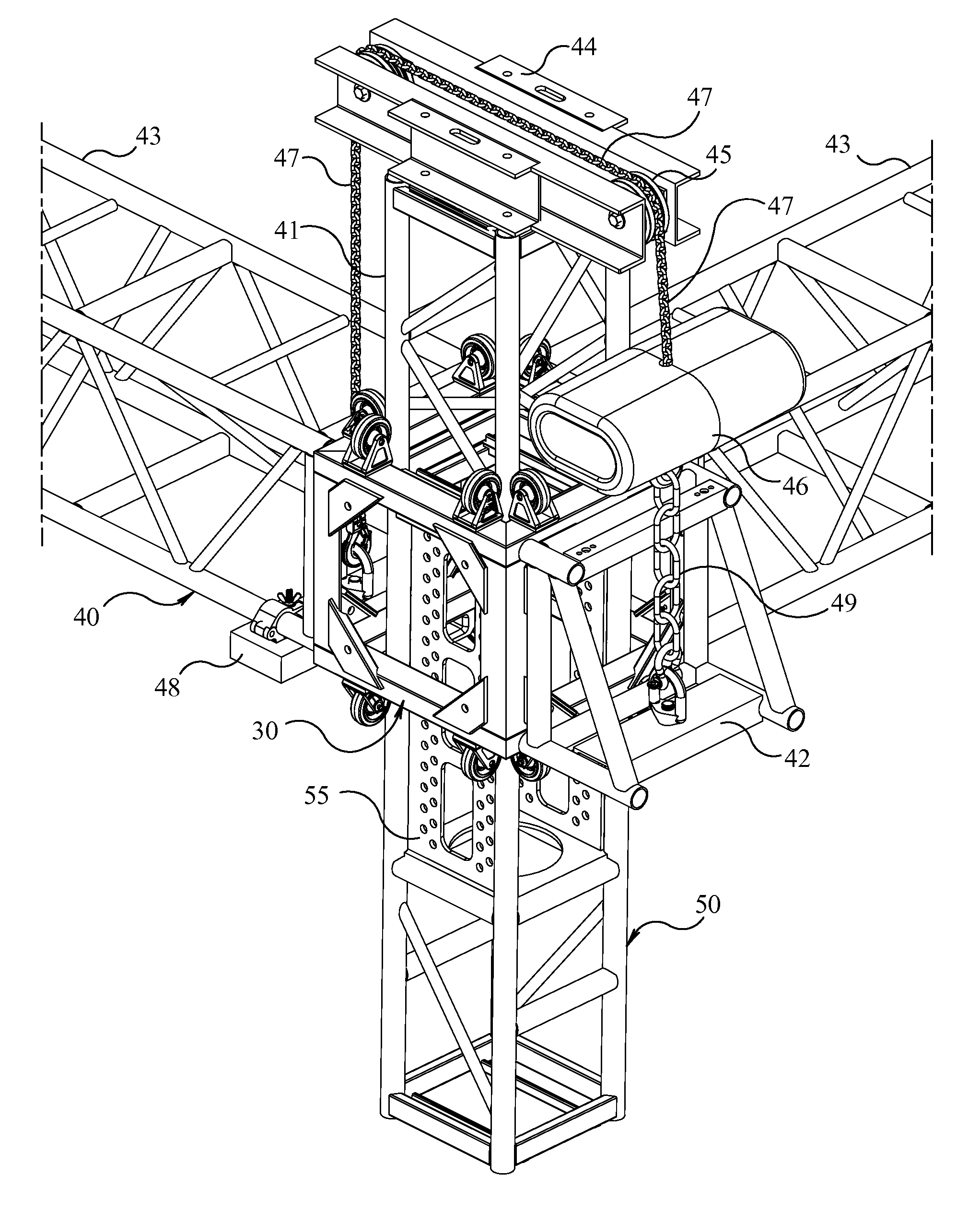
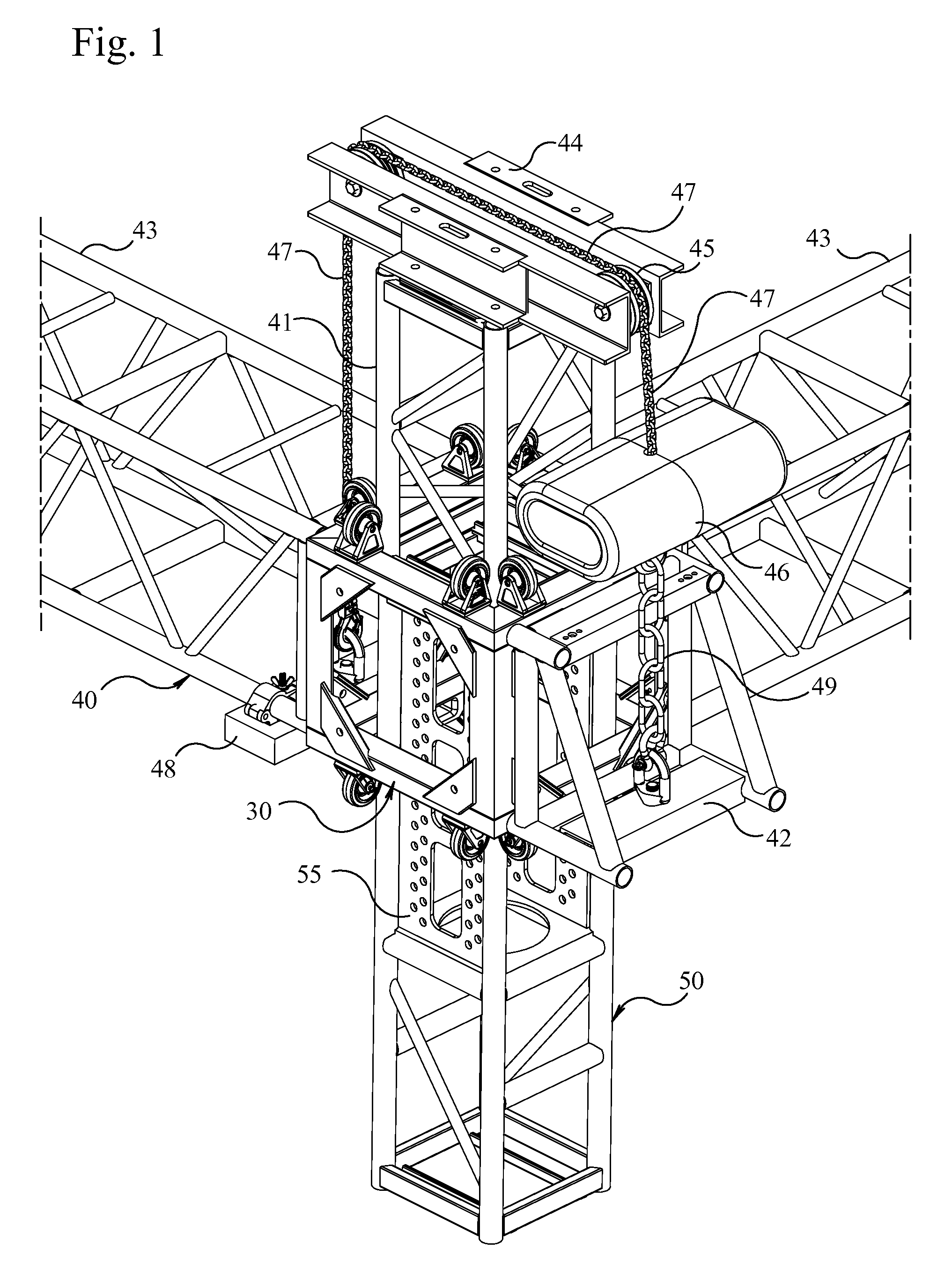
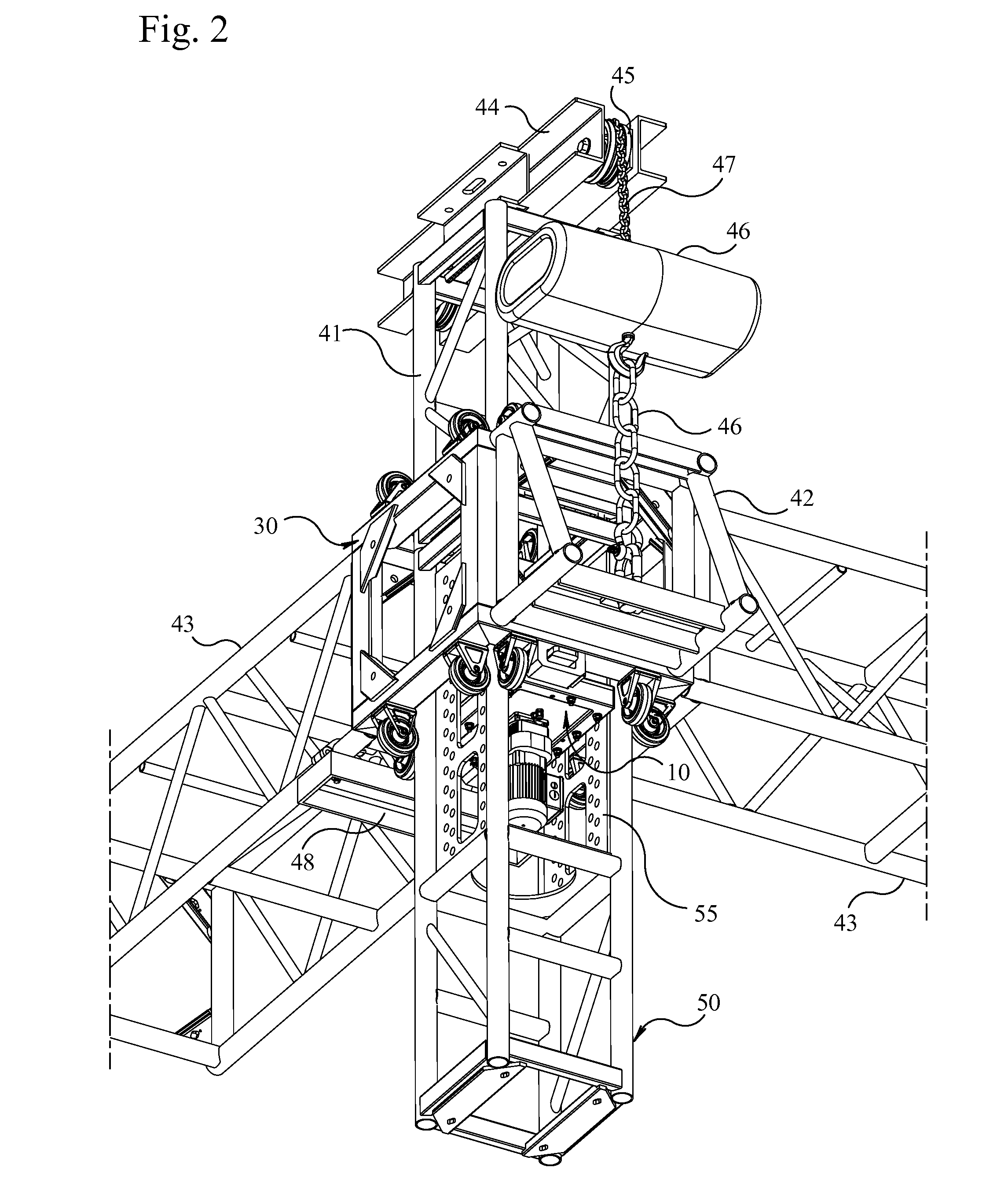
[0065]Turning now descriptively to the drawings, in which similar reference characters denote similar elements throughout the several views, the figures illustrate a remotely controlled locking mechanism that is mounted within a truss tower section with adjustable locations. The sleeve that slides or rolls up the tower is equipped with stirrups to provide a structural receptacle for the locking forks. The sleeve and the locking mechanism are equipped with sensors that indicate the sleeve is in the correct location for locking. The control system displays the status of the sensors and limit switches and uses logic to exercise the rules of operation.

[0066]FIG. 1: FIG. 1 is an overall perspective view of the first embodiment. This typical corner configuration of a self-climbing tower hoist is rigged in the normal fashion with sleeve with stirrups (30) and tower with lock mounting (50). The horizontal sections of truss (43) attach to the sleeve (31). The chain hoist lifting mechanism (4...


PUM


Abstract

A power lock system for stage truss towers for remotely locking a climbing truss sleeve block with its tower, thereby distributing the downward load directly into the tower and preventing upward motion. The power lock system for stage truss towers generally includes a remotely controlled locking mechanism that is mounted within a truss tower section with adjustable locations. The sleeve that slides or rolls up the tower is equipped with stirrups to provide a structural receptacle for the locking forks. The sleeve and the locking mechanism are equipped with sensors that indicate the sleeve is in the correct location for locking. The control system displays the status of the sensors and limit switches and uses logic to exercise the rules of operation.

Description

CROSS-REFERENCE TO RELATED APPLICATIONS[0001]This application claims the benefit of provisional patent application Ser. No. 61 / 875,937, filed Sep. 10, 2013 by the same inventor.BACKGROUND-PRIOR ART[0002]The following is a tabulation of some prior art that presently appears relevant:Patents[0003]U.S. Pat. No. 3,722,863 Lift Apparatus[0004]Mar. 27, 1973 Itoh et al[0005]U.S. Pat. No. 4,015,686 Portable Multi-stage Mechanical List[0006]Apr. 5, 1977 Bushnell, Jr.[0007]U.S. Pat. No. 4,484,421 Traveling Stage[0008]Nov. 27, 1984 Williams et al[0009]U.S. Pat. No. 5,551,199 Box Truss for Lights[0010]Sep. 3, 1996 Hayes et al[0011]U.S. Pat. No. 5,743,066 Box Truss for Ligths[0012]Apr. 28, 1998 Hayes et alNon-Patent Literature Documents[0013]ANSI E1.21-2013 Entertainment Technology—Temporary Structures Used for Technical Production of Outdoor Entertainment Events[0014]ANSI E1.2-2012 Entertainment Technology—Design, Manufacture and Use of Aluminum Trusses and Towers[0015]ANSI E1.6-3-2012 Selectio...

Claims


Application Information

Patent Timeline
IPC IPC(8): E04B1/343E04B1/41E04C3/08E04H12/18G05B19/05
CPCE04B1/34331E04B1/34384E04B1/40E04C2003/0486E04H12/18G05B19/058E04C3/08E04H3/24E04B1/388
Inventor DARDEN, BRUCE, W.
Owner DARDEN BRUCE WILLIAM
Why Eureka
Try Eureka