Wireless-charging base for charging in flat or inclined position

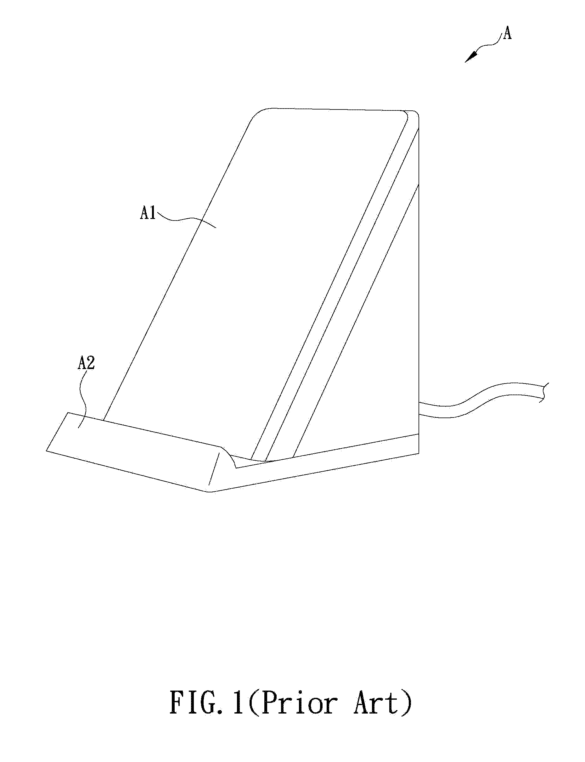
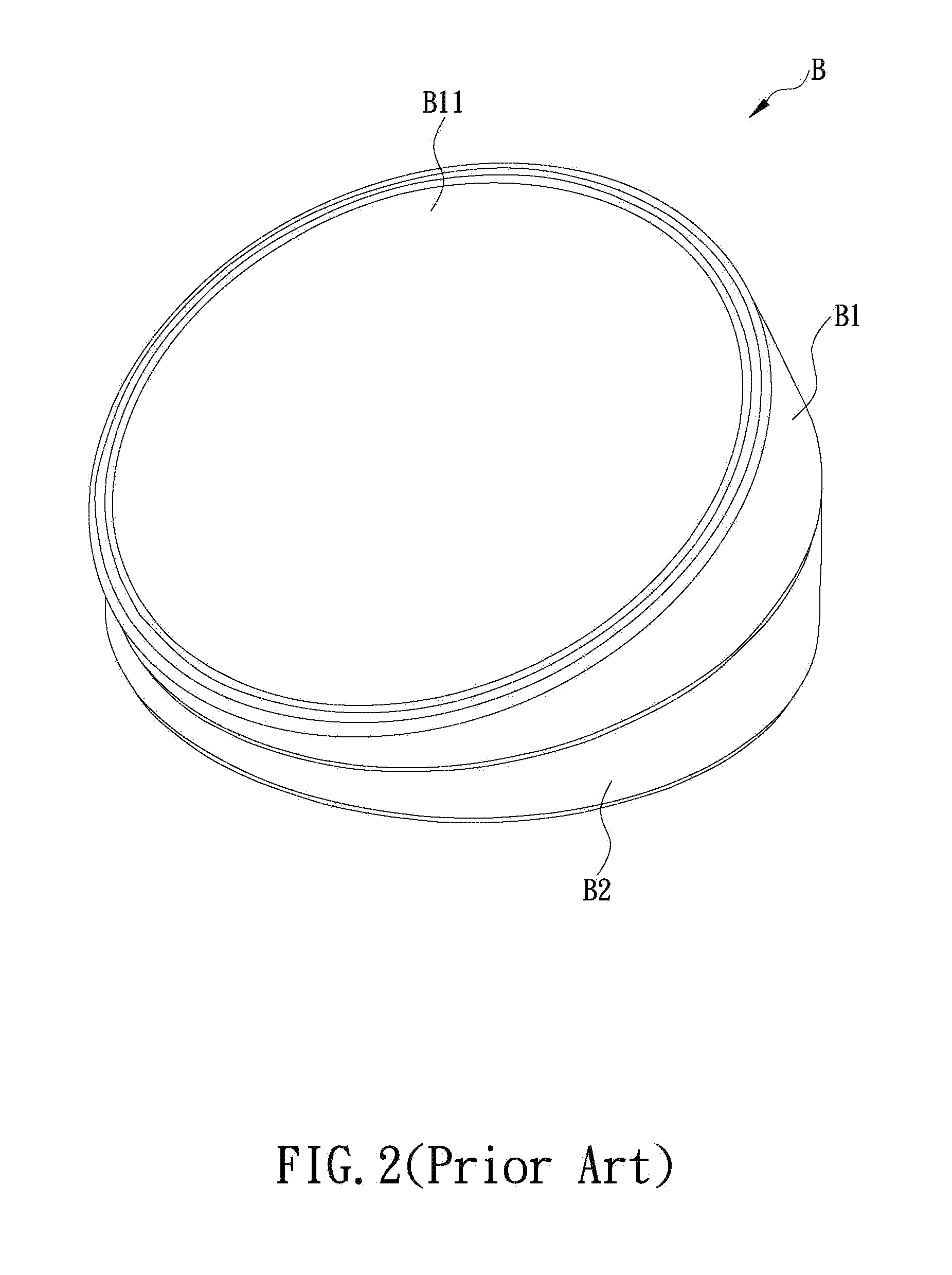
a technology of charging base and charging position, which is applied in the direction of electric vehicles, electric power, transportation and packaging, etc., can solve the problems of bulky wireless charging base a and irregular shape, and less convenient for users to carry, so as to promote the convenience and flexibility of wireless charging

Inactive Publication Date: 2016-03-03
ORTEK TECH
View PDF1 Cites 23 Cited by
  • Summary
  • Abstract
  • Description
  • Claims
  • Application Information

AI Technical Summary

Benefits of technology

[0007]In view of the bulky sizes of conventional wireless-charging bases that are less beneficial for users to carry, years of practice and numerous studies and tests have finally yielded a wireless-charging base of the present invention for charging in flat or inclined position expected to promote the convenience and usage flexibility of wireless charging by the novel structure.

Problems solved by technology

However, as may be seen from the figure, the wireless-charging base A is bulky and has an irregular shape which is less convenient for the user to carry.
Firstly, although the wireless-charging base B positions the smartphone via the friction force of the anti-slip pad, the smartphone may still be dislocated from the inclined surface B11 under impact by external forces, and may even tumble off along the inclined surface B11; secondly, although the first base body B1 may rotate against the second base body B2, such rotation only changes the inclination angle of the inclined surface B11, and cannot substantially change the volume and conformation of the wireless-charging base B, and thus the issue of inconvenience in carrying remains.

Method used


Image

  • Wireless-charging base for charging in flat or inclined position
  • Wireless-charging base for charging in flat or inclined position
  • Wireless-charging base for charging in flat or inclined position

Examples


Embodiment Construction

[0020]The principles, structural features, and purposes of the invention may be more fully understood by the subsequent detailed description and examples with references made to the accompanying drawings.

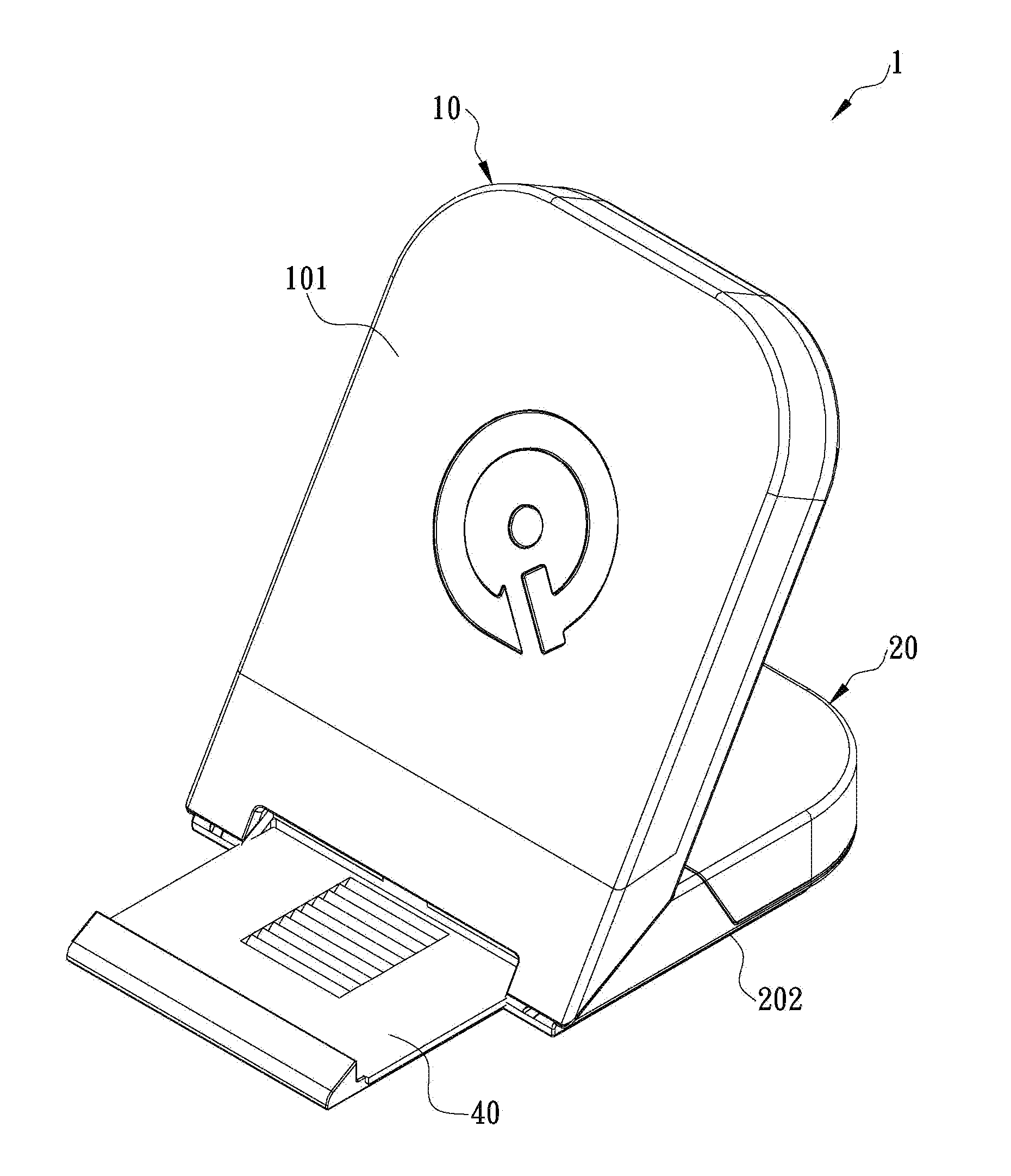
[0021]The invention pertains to a wireless-charging base for charging in flat or inclined position, and FIG. 3 and FIG. 4 show a first preferred embodiment of the invention. The wireless-charging base 1 comprises a first casing 10, a second casing 20, and a wireless-charging module 30, wherein an end of the first casing 10 is pivotally connected with an end of the second casing 20, so that the first casing 10 and the second casing 20 are assembled at an angle; the wireless-charging module 30 is installed in the first casing 10 and at least comprises a first coil 31, wherein the wireless-charging module 30 is connected to a power supply unit (e.g., a plug socket) via a cable to receive electric energy transmitted from the power supply unit and convert electric energy into electromagn...


PUM


Abstract

The present invention is to provide a wireless-charging base comprising a first casing, a second casing pivotally connected with the first casing, and a wireless-charging module installed in the first casing; wherein the first casing is configured to rotate against the second casing for allowing the base to be in a flat or an inclined supporting mode; in the flat supporting mode, bottom surfaces of the casings form a first surface for being placed on a plane, and top surfaces of the casings form a second surface for supporting an electronic device thereon; in the inclined supporting mode, the top surface of the first casing and the bottom surface of the second casing form an inclination angle for supporting the device; and a first coil in the module converts electric energy into electromagnetic fields and then transmits the electromagnetic fields to a second coil in the device through near-field induction.

Description

FIELD OF THE INVENTION[0001]The present invention relates to a wireless-charging base for charging in flat or inclined position, and more particularly to a wireless-charging base with two pivotally connected casings for allowing the wireless-charging base to be in a flat or an inclined supporting mode supporting an electronic device alternatively.BACKGROUND OF THE INVENTION[0002]As technologies rapidly develop in recent years, various novel electronic devices have been developed and produced one after another and have rendered daily living more convenient and comfortable, such as smartphones, electric vehicles, satellite navigation, event data recorders, etc. As these electronic devices are being used, they also gradually change our lifestyles; for example, since many of such electronic devices provides services via network connections, network signal stability has thus become a significant factor when evaluating the convenience and well-being of an environment. In addition, since s...

Claims


Application Information

Patent Timeline
Patent Type & Authority Applications(United States)
IPC IPC(8): H02J7/00H02J50/10
CPCH02J7/0042H02J7/025H02J7/0044H02J50/10
Inventor SHEU, UEN-HOURHUANG, CHI-TE
Owner ORTEK TECH
Why Eureka
Try Eureka