Rotatable vehicle seat frame assembly

a seat frame and rotating technology, applied in vehicle parts, vehicle arrangements, combination furniture, etc., can solve the problems of inconvenient conventional vehicles, vehicle cannot accommodate goods in large quantity or volume, and passengers are dangerous and uncomfortable, and achieve the effect of convenient convenience and applicability

Active Publication Date: 2015-12-31
ZHUHAI GUANZHE TECH CO LTD
View PDF0 Cites 12 Cited by
  • Summary
  • Abstract
  • Description
  • Claims
  • Application Information

AI Technical Summary

Benefits of technology

[0008]The main objective of the present invention is to provide a rotatable vehicle seat frame assembly that has multiple seat frames, which can be transformed between a passenger-mode and a cargo-mode to facilitate convenience and applicability.
[0010]The bottom sliding mechanisms, the top sliding mechanisms, the angle-adjusting mechanisms, and the leg rest assembly enable the seat frame to be rotated into a flattened status in a limited inner space of a vehicle, enable the seat frame to be transformed between a passenger-mode and a cargo-mode, and enable the seat frame to be used as a bed during a long trip. When in the passenger-mode, the position of the seat bracket and the angle of the back support bracket may be adjusted to facilitate convenience, and to provide more use modes in a limited inner space with the elevatable desk.

Problems solved by technology

If the user takes passengers on a vehicle designed for cargo, it is dangerous and uncomfortable for the passengers as the vehicle has no fixed passenger seats to sit on.
If the user loads cargo on a vehicle designed for passengers, the vehicle cannot accommodate goods in large quantity or volume as the fixed vehicle seats occupy most central parts of the back seat area.
As a result, for those who have both needs as mentioned above, the conventional vehicles are quite inconvenient.
Besides, passengers may need to lie semi-reclined or fully lie down in the vehicle during a medium or long trip, but it is hard for the conventional vehicle to provide this function since the inner space of the vehicle is limited.

Method used


Image

  • Rotatable vehicle seat frame assembly
  • Rotatable vehicle seat frame assembly
  • Rotatable vehicle seat frame assembly

Examples


Embodiment Construction

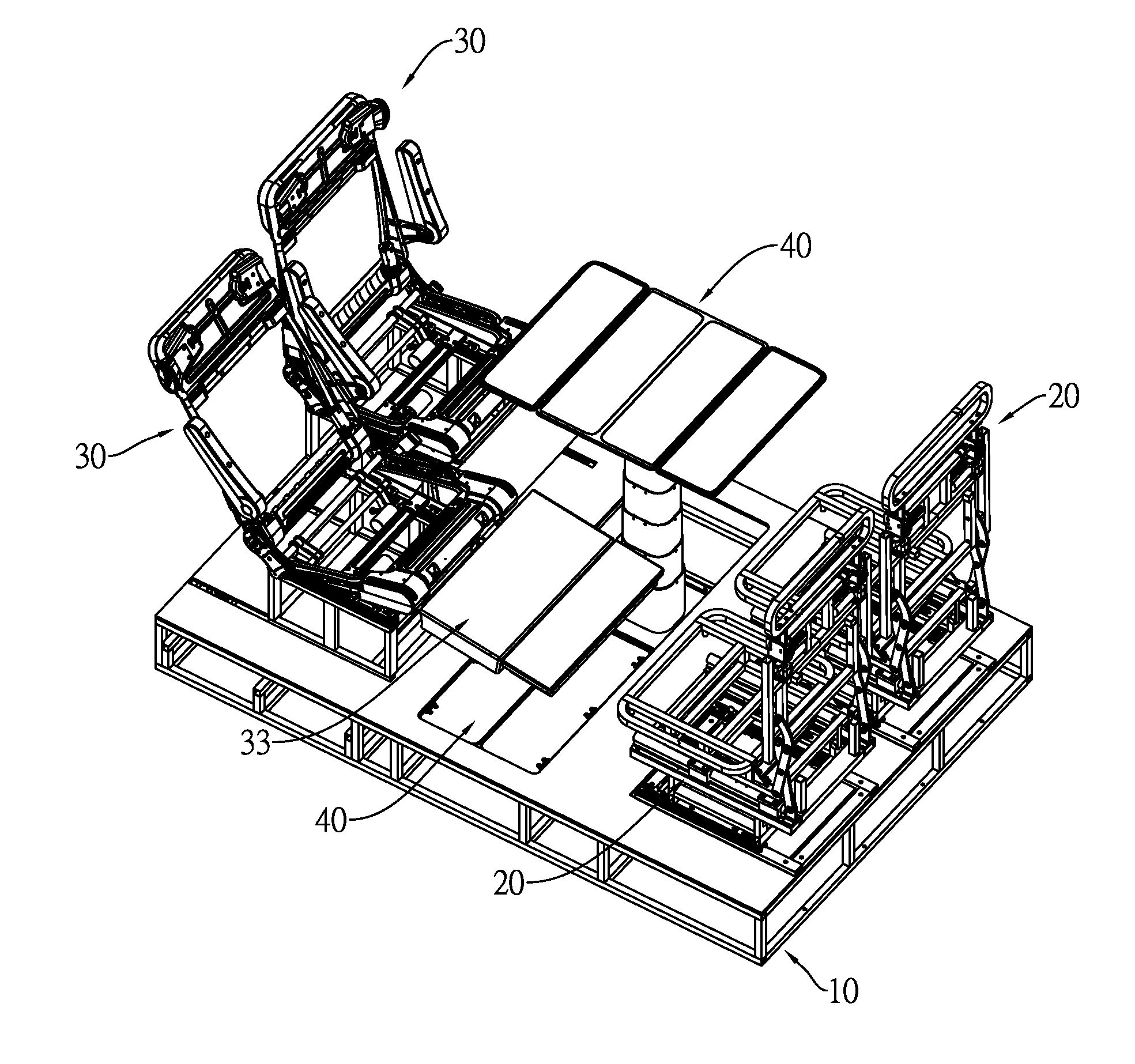
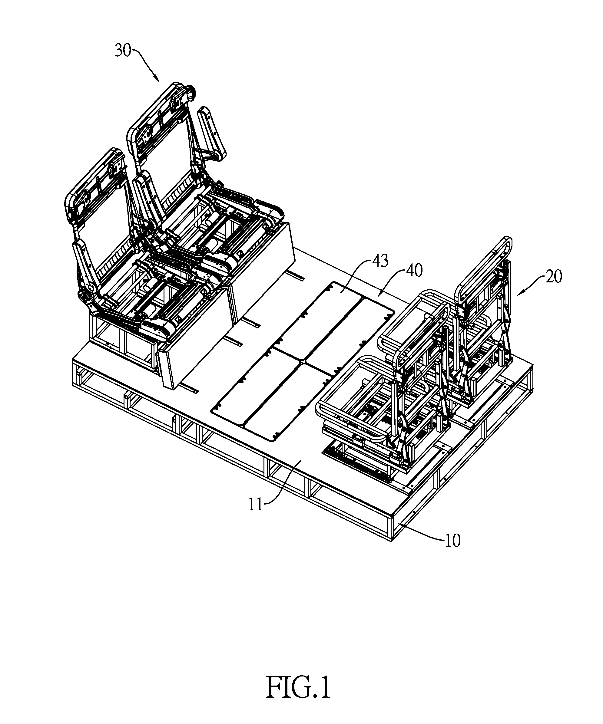
[0040]With reference to FIG. 1, a rotatable vehicle seat frame assembly in accordance with the present invention comprises a main frame 10, at least one first seat frame 20, at least one second seat frame 30, and at least one elevatable desk 40.

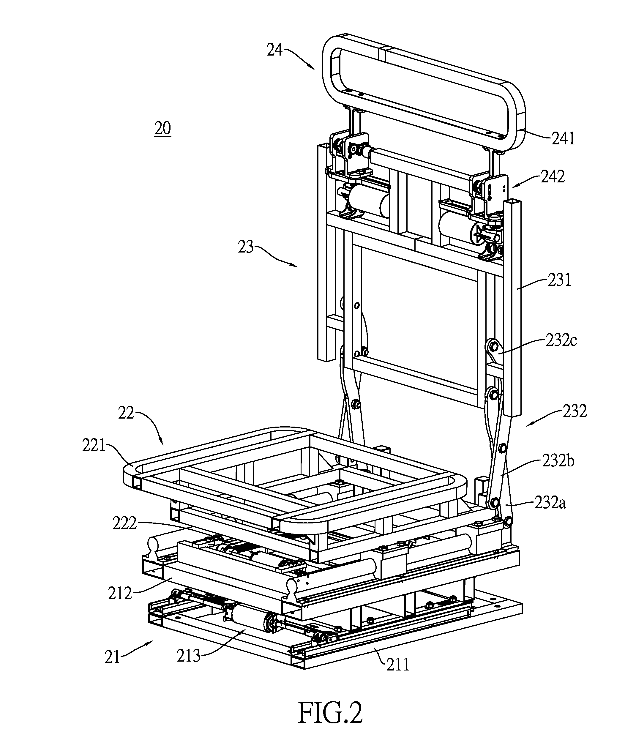
[0041]With reference to FIGS. 1 to 3, the at least one first seat frame 20 is mounted on a top surface 11 of the main frame 10. Each first seat frame 20 has a first stand assembly 21, a first seat assembly 22, a first back support assembly 23 and a first headrest assembly 24.

[0042]The first stand assembly 21 has a first base bracket 211, a first stand 212 and a first bottom sliding mechanism 213. The first stand 212 is slidably mounted on a top surface of the first base bracket 211. The first bottom sliding mechanism 213 is mounted between the first stand 212 and the first base bracket 211 to make the first stand 212 slidable relative to the first base bracket 211. In a preferred embodiment, the first bottom sliding mechanism 213 comprises a ...


PUM


Abstract

A rotatable vehicle seat frame assembly has a main frame, at least one first seat frame, at least one second seat frame, and at least one elevatable desk. Each seat frame has a bottom sliding mechanism, a top sliding mechanism, and an angle-adjusting mechanism. The second seat frame further has a leg rest assembly. The bottom sliding mechanisms, the top sliding mechanisms, the angle-adjusting mechanisms, and the leg rest assembly enable the seat frame to be rotated into a flattened status in a limited inner space of a vehicle, enable the seat frame to be transformed between a passenger-mode and a cargo-mode, and enable the seat frame to be used as a bed during a long trip. When in the passenger-mode, the position of the seat bracket and the angle of the back support bracket may be adjusted to facilitate convenience, and to provide more use modes in a limited inner space with the elevatable desk.

Description

CROSS-REFERENCE TO RELATED APPLICATIONS[0001]This application is based upon and claims priority under 35 U.S.C. 119 from China Patent Application No. 201410288699.6 filed on Jun. 26, 2014, which is hereby specifically incorporated herein by this reference thereto.BACKGROUND OF THE INVENTION[0002]1. Field of the Invention[0003]The present invention relates to a rotatable vehicle seat frame assembly, especially to a rotatable vehicle seat frame assembly that can be installed in the vehicle for users to be seated on.[0004]2. Description of the Prior Arts[0005]Vehicles generally include the following two types: the type designed for passengers and the type designed for cargo. Vehicles designed for passengers often have fixed vehicle seats in the back seat area for passengers, and have a relatively narrower accommodating space behind the fixed vehicle seats, which is for accommodating goods in small quantity or volume. Vehicles designed for cargo have no back seats in the back seat area ...

Claims


Application Information

Patent Timeline
Patent Type & Authority Applications(United States)
IPC IPC(8): B60N2/20B60N3/06B60N2/46B60N2/22B60N2/44B60N2/48B60N3/00B60N2/07B60N2/75B60N2/90
CPCB60N2/206B60N3/001B60N3/063B60N2/0722B60N2/22B60N2/838B60N2002/024B60N2/767B60N2/005B60N2/01B60N2/06B60N2/1615B60N2002/0236B60N2/995B60N2/02258B60N2/02253B60N2/12B60N2/3056B60N2/34B60N2/36B60N2002/0212
Inventor YIN, QING-KUNCHANG, CHIN-CHEN
Owner ZHUHAI GUANZHE TECH CO LTD
Why Eureka
Try Eureka