Interferometric Rayleigh Scattering Measurement System

a measurement system and interferometer technology, applied in the field of interferometric rayleigh scattering measurement system, can solve the problems of undesirable flow modification, inability to measure velocity in all environments, and inability to achieve the effect of increasing reliability and versatility, increasing accuracy and applicability, and reducing costs

Inactive Publication Date: 2008-02-21
NASA
View PDF11 Cites 25 Cited by
  • Summary
  • Abstract
  • Description
  • Claims
  • Application Information

AI Technical Summary

Benefits of technology

[0019]A significant advantage of the present invention is that it provides efficient measurement of multiple velocity components at multiple, spatial regions in a gas flow.
[0020]Another significant advantage of the present invention is that does not require seeding of the gas with particles or molecules.
[0021]A significant feature of the present invention is that it uses a single interferometer and a single imaging device thereby decreasing costs and increasing reliability and versatility.
[0022]Another significant advantage of the present invention is that the recirculation of the light rejected by the interferometer increases the accuracy and the applicability of the method for measurements at elevated temperatures specific to combustion processes without the requirement of increasing the laser energy.
[0023]Other significant advantages of the present invention are its robustness, and improved accuracy that result from recording both spectra of the Rayleigh scattered light and the reference laser light in a single interferogram.
[0024]Other objects and advantages of the present invention will become more obvious hereinafter in the specification and drawings.

Problems solved by technology

Most known methods for measuring the velocity do not work in all environments and, in some cases, require undesirable modifications to the flow.
However, seeding the flow with particles is undesirable since it is time consuming and increases cost.
Furthermore, it is not possible to seed some flows with particles.
Additionally, such particles do not always follow the gas flow, especially in supersonic and hypersonic flows and with vortices at any speed.
All of these molecular based known methods have disadvantages or limitations, namely, they: (i) are limited to a small class of flows, (ii) do not work well at high temperatures, (iii) cannot be used to measure three velocity components simultaneously using a single probing laser beam, (iv) sometimes requires specific molecules to be seeded into the flow, and (v) cannot be used easily to measure at multiple points.
However, this technique has limitations in that the spectroscopy of the iodine is fixed and the technique does not work well at high temperatures (e.g. >1000 K).
These limitations result in limited dynamic range.
However, due to low efficiency of the interferometer that is used to analyze the Rayleigh spectra, this technique is generally limited to time-averaged measurements of one component of velocity.
Furthermore, this requirement prevents those known systems from being configured as a compact system.
However, such a technique is complex and expensive to manufacture.
Furthermore, the use of such complex components prevents this known system from being compact and configured on a single platform.

Method used


Image

  • Interferometric Rayleigh Scattering Measurement System
  • Interferometric Rayleigh Scattering Measurement System
  • Interferometric Rayleigh Scattering Measurement System

Examples


example

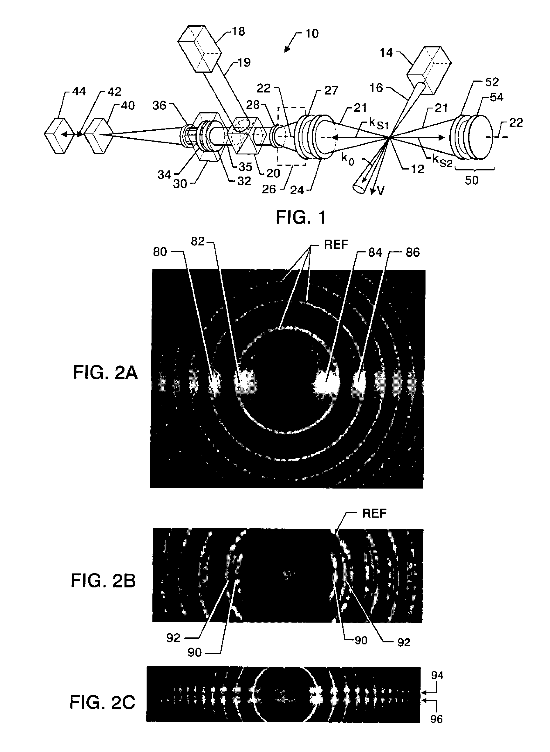
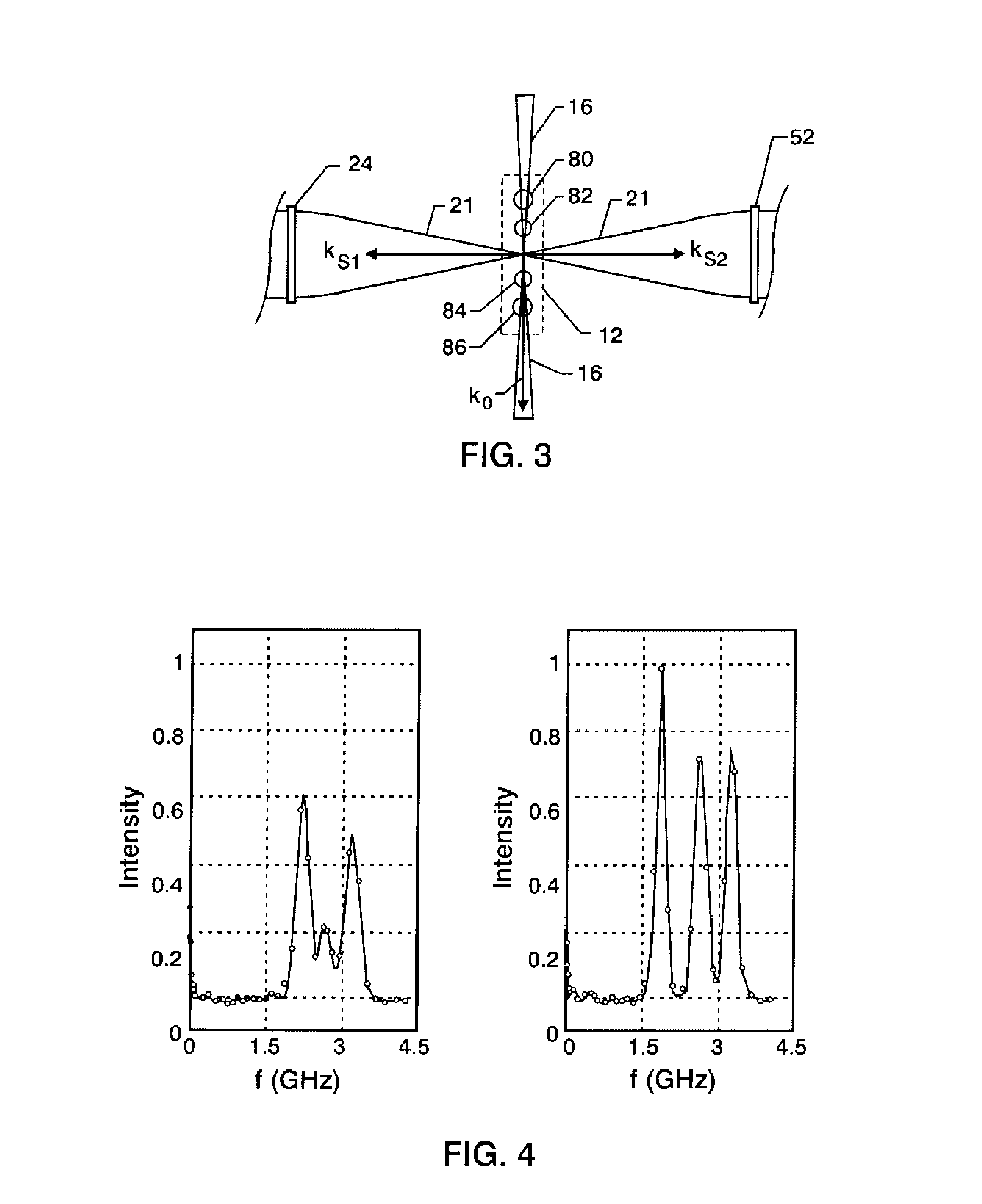
[0043]Referring to FIG. 2B, in order to compute the flow velocity, five rows were averaged through the center of the interferogram as described in the technical paper entitled “Intracavity Rayleigh-Mie Scattering For Multipoint, Two-Component Velocity Measurement,” by Bivolaru et al., Optics Letters, Vol. 31, No. 11, pp. 1645-1647, June, 2006, the disclosure of which article is herein incorporated by reference as if set forth in its entirety. This data was converted from the spatial domain (pixels) to the frequency domain. Two spectra processed in this way are shown in FIG. 4. Specifically, FIG. 4 shows spectra of Mie scattering from water clusters generated naturally in the flow.

[0044]Gaussian peaks were fitted to the five-row average slice to determine with sub-pixel resolution the location of the peaks and frequency. The low frequency peak, slightly above 3.0 GHz in the spectrum, is the reference laser frequency used to identify the zero-velocity fringe location. The first peak i...


PUM


Abstract

A method and apparatus for performing simultaneous multi-point measurements of multiple velocity components in a gas flow is described. Pulses of laser light are directed to a measurement region of unseeded gas to produce Rayleigh or Mie scattered light in a plurality of directions. The Rayleigh or Mie scattered light is collected from multiple directions and combined in a single collimated light beam. The Rayleigh or Mie scattered light is then mixed together with a reference laser light before it is passed through a single planar Fabry-Perot interferometer for spectral analysis. At the output of the interferometer, a high-sensitivity CCD camera images the interference fringe pattern. This pattern contains the spectral and spatial information from both the Rayleigh scattered light and the reference laser light. Interferogram processing software extracts and analyzes spectral profiles to determine the velocity components of the gas flow at multiple points in the measurement region. The Rayleigh light rejected by the interferometer is recirculated to increase the accuracy and the applicability of the method for measurements at high temperatures without requiring an increase in the laser energy.

Description

ORIGIN OF THE INVENTION[0001]This invention described herein was made in part by employees of the United States Government and may be manufactured and used by or for the Government of the United States of America for governmental purposes without the payment of any royalties thereon or therefor.BACKGROUND OF THE INVENTION[0002]1. Field of the Invention[0003]The present invention generally relates to a method and apparatus for performing simultaneous multi-point measurements of multiple velocity components in an unseeded flow.[0004]2. Description of Related Art[0005]Gas flow velocity is an important parameter to measure in scientific, engineering and industrial applications. The velocity field dominates effects such as heat transfer, aerodynamics, and mass transport. Most known methods for measuring the velocity do not work in all environments and, in some cases, require undesirable modifications to the flow. For example, many known techniques require that particles or gasses be seed...

Claims


Application Information

Patent Timeline
Patent Type & Authority Applications(United States)
IPC IPC(8): G01P3/36
CPCG01P5/26G01P13/02G01S17/58
Inventor BIVOLARU, DANIELDANEHY, PAUL M.LEE, JOSEPH W.
Owner NASA
Why Eureka
Try Eureka