Anti-counterfeit sealing cap with identification capability

a technology of anti-counterfeit sealing cap and identification capability, which is applied in the direction of burglar alarm mechanical actuation, protective material radiating elements, instruments, etc., can solve the problems of difficulty in mass production and processing of data, storage space, and easy detection of unauthorized opening and resealing of bottles, so as to increase detection sensitivity, effective measure against counterfeiting, and the effect of large effective area of the antenna

Active Publication Date: 2006-03-09
MEDIATEK INC
View PDF2 Cites 54 Cited by
  • Summary
  • Abstract
  • Description
  • Claims
  • Application Information

AI Technical Summary

Benefits of technology

[0012] By the design of the present invention, the cap body as a whole serves as an effective area of the antenna, ensuring a large effective area of the antenna and an unrestricted angle of radiation, increasing detecting sensitivity. Automatic destruction of the identifying chip upon opening of the cap body serves as an effective measure against counterfeiting.
[0013] Furthermore, the identifying chip can be read repeatedly without opening the cap, thus being suitable for use in mass production.

Problems solved by technology

Usually, caps of liquid bottles are equipped with protective measures and techniques, as follows: 1. A protective ring is attached at a lower edge of a cap, which is destroyed upon any attempt to open the bottle, so that unauthorized opening and resealing of the bottle is easily detected, by which the contents thereof may have been exchanged.
However, examining of bottles has to be performed manually, there are no specific product data stored, and bottles have to be examined one by one, resulting in difficulties for mass production and processing of data.
This method, however, requires a bar code reader, storage space is limited, so that detailed information has to be stored elsewhere, e.g., on a server computer, and are not immediately accessible.
Furthermore, reading bar codes requires optical scanning of samples one by one and is therefore not suitable for quick processing of large volumes.
The chip is read out only once and then destroys itself, so that there is only a one-time reading capability, not allowing for repeated reading of data.
However, the antenna of this RFID device has a limited area, which restricts an angle of reading, and the chip is not protected from being dismounted and reinserted in counterfeit products, so that no effective protection against pirating is achieved.
Furthermore, the chip is only usable once for reading and uses its readability immediately after that.
But for the distribution of goods, reading of information is often required at various stages, which cannot be performed from conventional chips.

Method used


Image

  • Anti-counterfeit sealing cap with identification capability
  • Anti-counterfeit sealing cap with identification capability
  • Anti-counterfeit sealing cap with identification capability

Examples


first embodiment

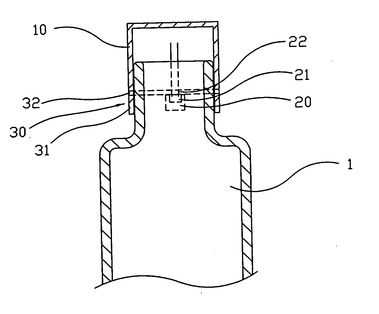
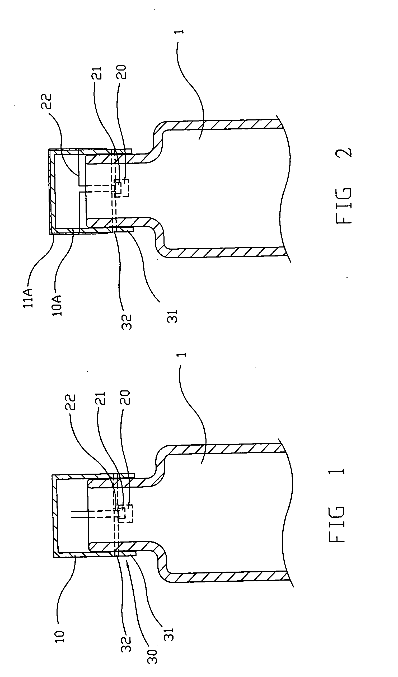
[0015] As shown in FIG. 1, the anti-counterfeit sealing cap with identification capability of the present invention in a first embodiment mainly comprises: a cap body 10, sealing an opening of a container 1 and having a surface; a semiconductor identifying chip 20, attached to an inner side of the cap body 10, storing product data; and a destructing device 30. The identifying chip 20 has a signal emitting device 21. Several connectors 22 connect the signal emitting device 21 and the cap body 10, so that signals generated by the signal emitting device 21 are radiated by the cap body 10 serving as an antenna to a reader in an RFID device for frequency identification. The destructing device 30 is mounted between the cap body 10 and the container 1. Upon opening the cap body 10, the destructing device 30 destroys the capability of the identifying chip20 to send signals, preventing unauthorized opening and reuse of the cap body 10.

[0016] The identifying chip 20 works similarly to convent...

second embodiment

[0021] Referring to FIG. 2, the present invention in a second embodiment has a cap body 10A made of plastics or another electrically non-conductive material. An antenna 11A made of electrically conductive material covers a large part of the cap body 10A. Electrical connection between the signal emitting device 21 of the identifying chip 20 and the antenna 11A is established by the connectors 22. Preferably, the antenna 11A is a metal plate or is printed on the cap body 10A.

[0022] In the first and second embodiments, the present invention has antennas of nearly equal areas, resulting in nearly equal signal effectivities. The second embodiment of the present invention, however, due to the applicability of plastic caps allows for a wider range of applications.

third embodiment

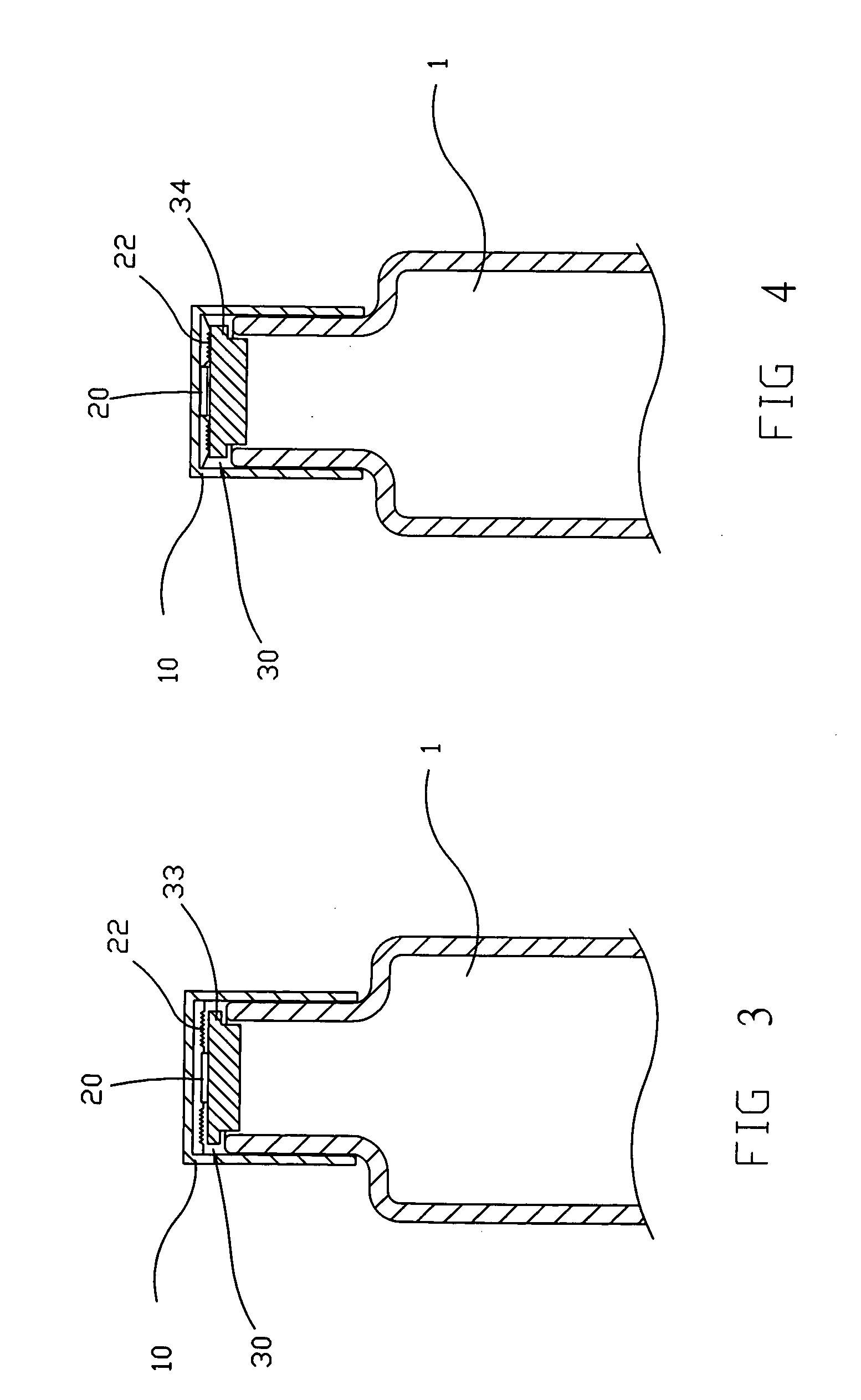
[0023] Furthermore, as shown in FIG. 3, in the present invention, the destructing device 30 has a plug 33 sealing the container 1. After removing the cap body 10, the plug 33 is separated therefrom. At least one part of the identifying chip 20 is connected with the plug 33, while via the connectors 22 being connected with the cap body 10 or the antenna. Therefore, when the cap body 10 is removed, the identifying chip 20 is tom apart or the connectors 22 break, eliminating any signal emission capability.

[0024] Referring to FIG. 4, in a fourth embodiment of the present invention, the destructing device 30 has a plug 34 which is separate from the cap body 10. In contrast to the third embodiment of the present invention, the identifying chip 20 is mounted on the inner side of the cap body 10 and at least one of the connectors 22 is connected with the plug 34. Therefore, when the cap body 10 is opened, the connectors 22 break, and no transmission of signals from the identifying chip 20 t...


PUM


Abstract

A sealing cap with an anti-counterfeit and identification capability comprises a cap body, an identification chip with a signal emitting device generating an identification signal, and a destructive device, characterized in that the cap body is electrically connected with the signal generating device and serves as an antenna of a relatively large area and in that the destructive device after dismounting of the cap destroys the capability to emit radiation and thus prevents said identifying chip from being dismounted and reused.

Description

BACKGROUND OF THE INVENTION [0001] 1. Field of the Invention [0002] The present invention relates to an anti-counterfeit sealing cap with identification capability, particularly to an anti-counterfeit sealing cap with wireless frequency identification capability. [0003] 2. Description of Related Art [0004] Spirits, beverages, cosmetics and other valuable liquids need protection against counterfeit and theft during transport. Usually, caps of liquid bottles are equipped with protective measures and techniques, as follows: 1. A protective ring is attached at a lower edge of a cap, which is destroyed upon any attempt to open the bottle, so that unauthorized opening and resealing of the bottle is easily detected, by which the contents thereof may have been exchanged. 2. Characters or drawings are printed on the cap which are invisible under normal light, but visible under ultraviolet light, thus identifying the bottle as a genuine product. 3. Three-dimensional printing and a polishing t...

Claims


Application Information

Patent Timeline
Patent Type & Authority Applications(United States)
IPC IPC(8): G08B13/14G06K19/06
CPCB65D55/028B65D2203/10Y10S215/901G06K19/073G06K19/07798G06K19/04G08B13/14
Inventor CHEN, LI-HUEIGWO, TSUNG-JUWANG, FENG-HEHCHEN, CHIEN-BEN
Owner MEDIATEK INC
Why Eureka
Try Eureka