External cavity tunable compact mid-IR laser

a compact, infrared technology, applied in the direction of lasers, lasers, semiconductor lasers, etc., can solve the problems of affecting the development of mir laser devices, affecting the actual application of mir lasers, and limiting the auger recombination, so as to achieve effective cooling, avoid moisture, and facilitate use

Active Publication Date: 2007-02-08
DAYLIGHT SOLUTIONS
View PDF36 Cites 90 Cited by
  • Summary
  • Abstract
  • Description
  • Claims
  • Application Information

AI Technical Summary

Benefits of technology

[0050] In accordance with still other embodiments of the invention, there is provided a tunable MIR laser device which has a hermetically sealed housing. The housing may be filled with an inert gas and is designed primarily to keep out moisture. The housing has a window which is transparent to the laser light so that the laser light may exit the window to the exterior of the housing. To permit ease of use and generally applicability of the laser device the housing is designed to have dimensions of approximately 20 cm (height)×20 cm (width)×20 cm (length) or less, where the length is taken along a direction of propagation of the laser light. The tunable Mid-IR laser device further has a thermo electric cooling (TEC) device which is also fully contained within the housing and a heat spreader. The heat spreader is mounted within the housing and is thermally coupled to the TEC device. A quantum cascade laser gain medium is utilized as the preferred lasing medium. The quantum cascade laser gain medium is contained within the housing and is thermally coupled to the heat spreader. The heat spreader is positioned intermediate the TEC device and the quantum cascade laser gain medium. The heat spreader is used to distribute the relatively large amount of heat generated by the quantum cascade laser gain medium to the TEC device to effectively cool the quantum cascade laser gain medium to permit it to operate efficiently at a controlled temperature and for a relatively long useful life. The tunable MIR laser device also includes an output lens contained within the housing and secured at a position away from a laser emitting surface of the quantum cascade laser gain medium equal to a focal length of the output lens so as to collimate light output from the quantum cascade laser gain medium and direct the collimated laser beam to an exterior of the housing through the optical window. A filter, such as a grating, and a filter support, such as a grating support are also provided. The filter and filter support are contained within the housing, and the filter is operative for selecting one of a plurality of wavelengths from the quantum cascade laser gain medium and feeding back to the quantum cascade laser gain medium the selected wavelength so as to tune the quantum cascade laser gain medium. A filter lens is also provided and contained within the housing. If the filter is a grating, the filter lens is a grating lens. The filter lens may be similarly constructed and dimensioned as the output lens. The filter lens is secured at a position away from the laser emitting surface of the quantum cascade laser gain medium equal to a focal length of the filter lens so as to collimate light output from the quantum cascade laser gain medium and direct the collimated laser light to the filter. The output lens and the filter lens are each relatively small so as to fit within the housing and are chosen to have a diameter of approximately 10 mm or less. The output lens, the quantum cascade laser gain medium, the filter support and the filter lens are fixedly positioned with respect to one another. A rigid optical platform is utilized to fixedly secure these elements.
[0051] The external cavity tunable MIR laser device, in accordance with principles of embodiments of the invention, is very compact and light weight, and uses a quantum cascade laser gain medium as the laser gain medium. The quantum cascade laser gain medium may be selected for the particular application of interest within the frequency range of 3-12 μm by appropriate selection of the thickness of quantum wells and barriers and may be tuned over the frequency range of interest. Such a tunable compact, MIR laser enables a number of instruments to be developed in the fields of medical diagnostics, homeland security, and industrial processing, all based on laser absorption spectroscopy for molecular detection. Important characteristics of the tunable MIR device is the use of a quantum laser as the laser gain media, short focal length aspheric lens, for both the output lens and the filter lens (external cavity lens) enhanced cooling techniques that do not require liquid nitrogen and the use of high integration and packaging. The resulting structure presents a foot print that is extremely small with a package size (housing size) of approximately 20 cm (height)×20 cm (width)×20 cm (length) or less. The length is taken along the optical axis, which is the laser propagation direction. The packages size may be any integer or fraction thereof between approximately 1-20 cm for the length dimension combined with any integer or fraction thereof between approximately 1-20 cm in width dimension combined with any integer or fraction thereof between approximately 1-20 cm in the height dimension. A preferred footprint is approximately 3 cm (height)×4 cm (width)×6 cm (length) for the laser package, where the 6 cm is taken along the beam propagation direction.
[0052] Some advantages of the MIR device according to embodiments of the invention include high brightness with diffraction limited spatial properties and a narrow spectral width (<100 MHz=0.003 cm−1). The quantum laser gain medium enables high output power (50 mW) and allows easy modulation at high frequency with very low chirp. The packaging technology is mechanically and environmentally robust with excellent thermal properties and provides for dramatic miniaturization.

Problems solved by technology

Actual application of MIR lasers has been more limited and hampered by bulky size and cost of these devices.
While Type II QCLs have demonstrated room temperature CW operation between 3.3 and 4.2 μm, they are still limited by Auger recombination.
The development of small MIR laser devices has been hampered by the need to cryogenically cool the MIR lasers (utilizing, for example, a large liquid nitrogen supply) and by the relatively large size of such devices hampering their portability and facility of use and thus limiting their applicability.
The diffraction limited performance and ray tracing within the cavity permits selection of lens final parameters dependent on the choice of lens material.
Frequency modulation places sidebands about the center frequency, and during the wavelength scanning a strong RF modulation may be observed when off resonance due to an imbalance in the absorption of the frequency sidebands.
This is especially important in quantum cascade lasers which present a fairly low impedance and thus the reactance of the connections will critically limit the speed with which the device can be modulated.
The circuit design as disclosed herein presents an extremely small footprint for connections of the RF input to the quantum cascade laser.

Method used


Image

  • External cavity tunable compact mid-IR laser
  • External cavity tunable compact mid-IR laser
  • External cavity tunable compact mid-IR laser

Examples


Embodiment Construction

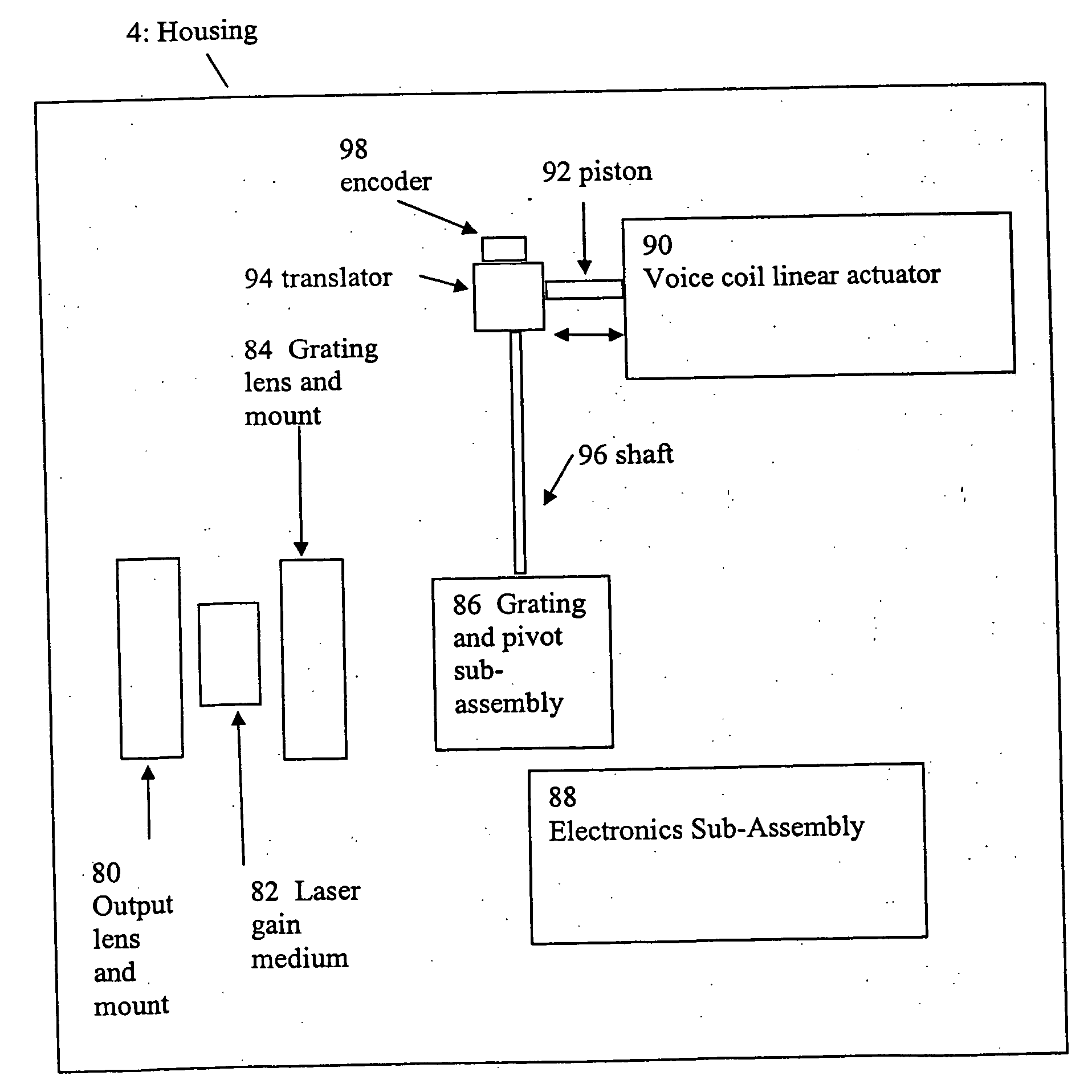
[0072] Embodiments of the invention expand upon the basic description of the MIR laser set forth above and forming part of the above referenced co-pending application which is incorporated herein in its entirety by reference. Common elements are identified by the same reference numeral throughout. The laser gain medium 6 utilized in FIGS. 1-5 is now replaced with a quantum cascade laser gain medium 6a which has an anti-reflective coating on the side of the laser chip facing the external cavity so that the wavelength dependent filter of the external cavity now serves as the fully or partially reflecting mirror for the laser.

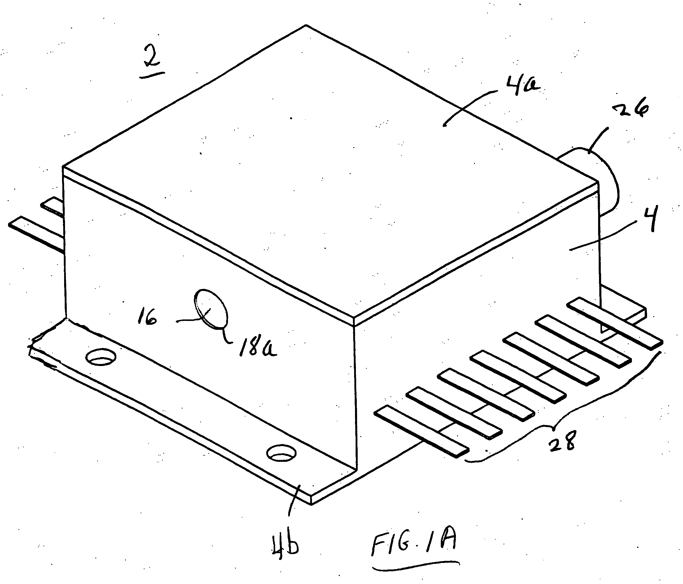
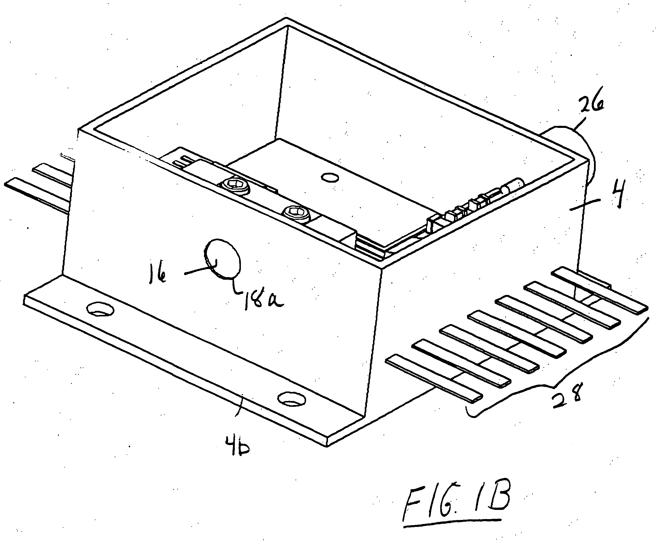
[0073] Embodiments of the invention may be seen in FIGS. 6-9. FIG. 6 shows a perspective view of the MIR laser 2, and FIGS. 7A and 7B show exploded perspective views similar to that of FIGS. 2A and 2B. FIG. 8 shows a plan view of an assembled external cavity tunable MIR laser with the top cover plate 4a removed to reveal the interior. FIG. 9A shows a cross sectio...


PUM


Abstract

A compact mid-IR laser device utilizes an external cavity to tune the laser. The external cavity may employ a Littrow or Littman cavity arrangement. In the Littrow cavity arrangement, a filter, such as a grating, is rotated to provide wavelength gain medium selectivity. In the Littman cavity arrangement, a reflector is rotated to provide tuning. A quantum cascade laser gain medium provides mid-IR frequencies suitable for use in molecular detection by signature absorption spectra. The compact nature of the device is obtained owing to an efficient heat transfer structure, the use of a small diameter aspheric lens for both the output lens and the external cavity lens and a monolithic assembly structure to hold the optical elements in a fixed position relative to one another. The compact housing size may be approximately 20 cm×20 cm×20 cm or less. Efficient heat transfer is achieved using a thermoelectric cooler TEC combined with a high thermal conductivity heat spreader onto which the quantum cascade laser gain medium is thermally coupled. The heat spreader not only serves to dissipate heat and conduct same to the TEC, but also serves as an optical platform to secure the optical elements within the housing in a fixed relationship relative on one another. The small diameter aspheric output and external cavity lens each may have a diameter of 10 mm or less and each lens is positioned to provided a collimated beam output from the quantum cascade laser gain medium. The housing is hermetically sealed to provide a rugged, light weight portable MIR laser source.

Description

BACKGROUND OF THE INVENTION [0001] 1. Field of the Invention [0002] Embodiments of the invention relate to a compact Mid-Infrared (MIR) laser device which is tunable utilizing an external cavity. The laser device finds applications in many fields such as, molecular detection and imaging instruments for use in medical diagnostics, pollution monitoring, leak detection, analytical instruments, homeland security and industrial process control. Embodiments of the invention are also applicable to the detection of molecules found in human breath; such molecules correlate to existing health problems such as asthma, kidney disorders and renal failure. [0003] 2. Description of Related Art [0004] MIR lasers of interest herein may be defined as lasers having a laser output wavelength in the range of approximately 3-12 μ / m (3333−833 cm−1). More broadly, however, “MIR” may be defined as wavelengths within a range of 3-30 μm. The far-IR is generally considered 30-300 μm, whereas the near IR is gen...

Claims


Application Information

Patent Timeline
Patent Type & Authority Applications(United States)
IPC IPC(8): H01S3/30H01S3/04H01S3/08
CPCB82Y20/00H01S3/1055H01S5/02216H01S5/02252H01S5/02288H01S5/02415H01S5/3402H01S5/02492H01S5/0427H01S5/06226H01S5/141H01S5/143H01S5/02438H01S5/02326H01S5/02253
Inventor DAY, TIMOTHYARNONE, DAVID F.
Owner DAYLIGHT SOLUTIONS
Why Eureka
Try Eureka