Composite sensor device and method of producing the same

a sensor device and composite technology, applied in the direction of turn-sensitive devices, acceleration measurement using interia forces, instruments, etc., can solve the problems of vibrator formation, deterioration of detection sensitivity of angular velocity sensors, undesirable sensitivities for acceleration detection,

Inactive Publication Date: 2006-02-28
MURATA MFG CO LTD
View PDF10 Cites 90 Cited by
  • Summary
  • Abstract
  • Description
  • Claims
  • Application Information

AI Technical Summary

Benefits of technology

[0011]It is an object of the present invention to solve the above problems, and more particularly, to provide a composite sensor device in which both of the detection sensitivities of the angular velocity sensor and the acceleration sensor can be enhanced, and to provide a method of producing the composite sensor device.

Problems solved by technology

However, the composite sensor devices proposed as described above have the problems that the sensitivities for detection of an acceleration are undesirable.
However, the fine vibrator formed in a micro-machining technique is significantly influenced with damping caused by air.
As a result, the detection sensitivity of the angular velocity sensor is remarkably deteriorated.
However, if the movable member of the acceleration sensor is vibrated at a high frequency and a large amplitude due to the transmitted vibration of the vibrator of the angular velocity sensor, as described above, the vibration at the high frequency becomes noisy, causing the problem that the acceleration can not be detected at a high sensitivity.
Thus, there arises the problem that the acceleration can not be accurately detected.

Method used


Image

  • Composite sensor device and method of producing the same
  • Composite sensor device and method of producing the same
  • Composite sensor device and method of producing the same

Examples


Embodiment Construction

[0024]Hereinafter, embodiments of the present invention will be described with reference to the drawings.

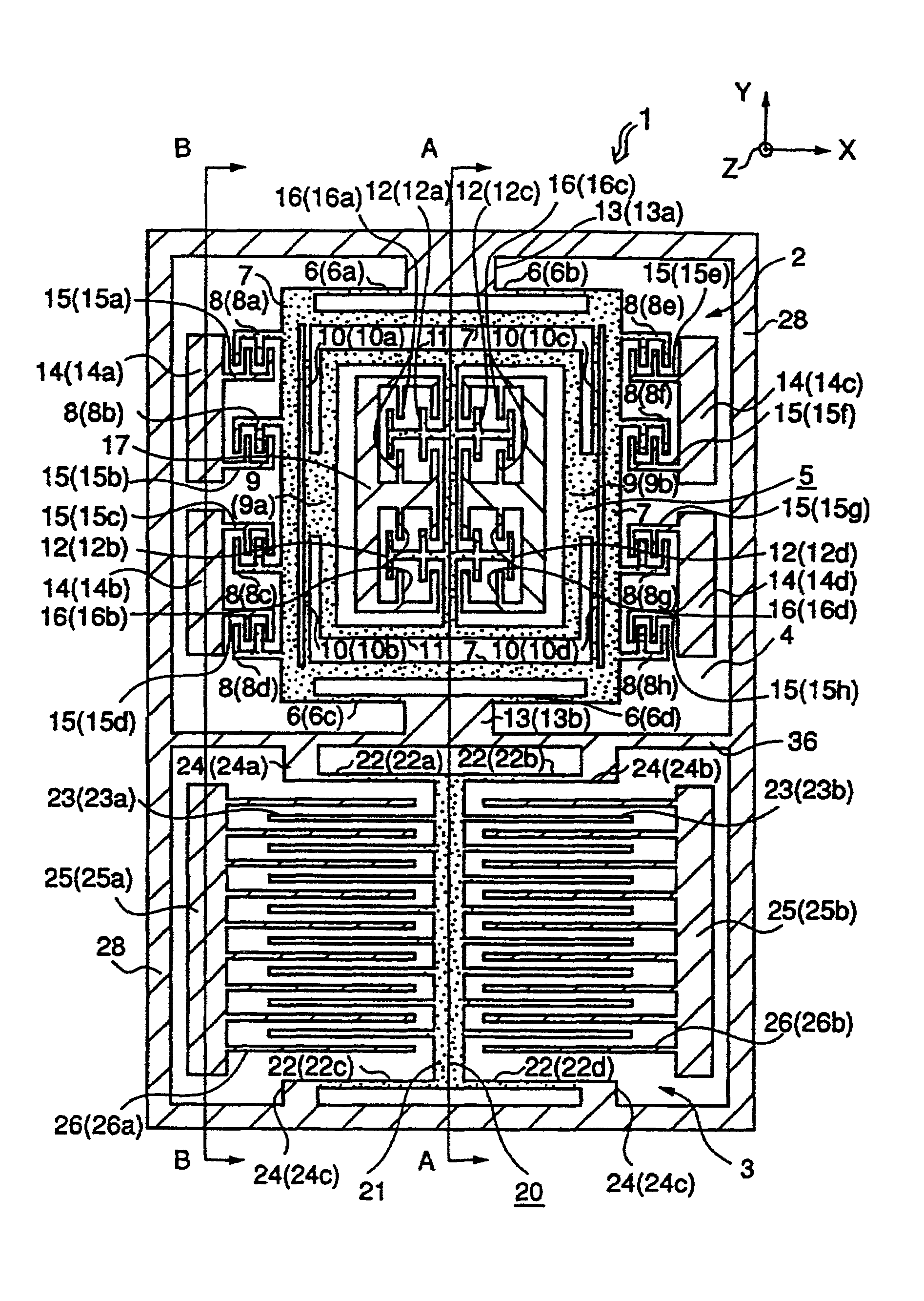
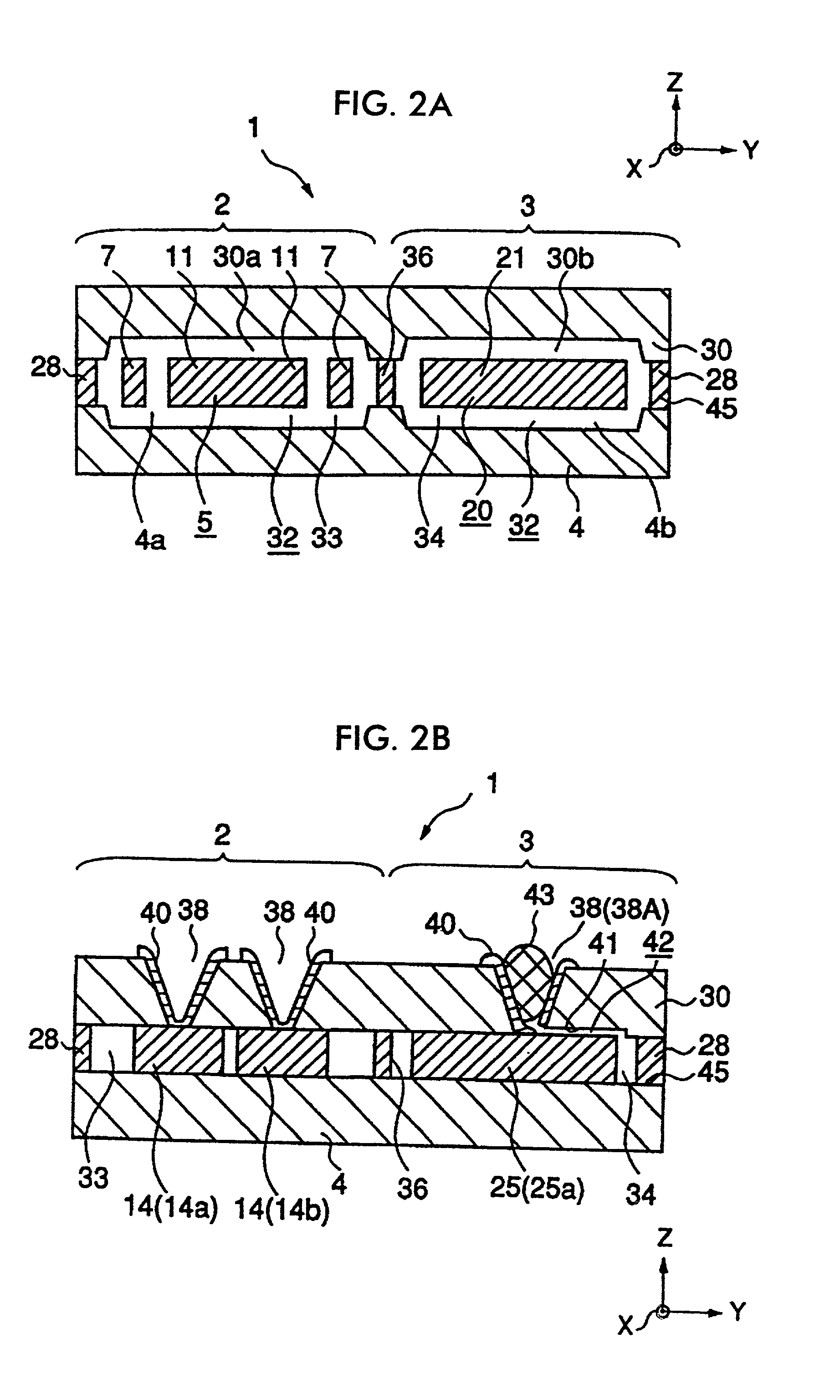
[0025]FIG. 1 is a schematic plan view of a composite sensor device according to an embodiment of the present invention. FIG. 2A is a schematic cross section of the part of the composite sensor device taken along line A—A in FIG. 1. FIG. 2B is a schematic cross section of the part of the composite sensor device taken along line B—B in FIG. 1.

[0026]A composite sensor device 1 shown in FIG. 1 and FIGS. 2A and 2B comprises an angular velocity sensor 2 and an acceleration sensor 3 formed integrally with each other. The composite sensor device 1 is formed by using a glass substrate 4 as a base, a glass substrate 30 as a lid, and a silicon substrate 45 as a displacement portion forming member.

[0027]The angular velocity sensor 2 in this embodiment contains a plane vibrator 5 as the vibrator of the angular velocity sensor. The plane vibrator 5 is formed by processing the silicon substrate...


PUM


Abstract

A plane vibrator of an angular velocity sensor and a movable member of an acceleration sensor are provided in a spaced floating state on the same substrate. A lid is formed so as to cover and be spaced from the upper side of the plane vibrator and the movable member. A space defined by the substrate and the lid is sectioned into a angular velocity sensor space and an acceleration sensor space by use of a sectioning wall. The angular velocity sensor space is hermetically sealed to be in the vacuum state. The acceleration sensor space is hermetically sealed to be under atmospheric pressure. The plane vibrator is vibrated at a high frequency and a large amplitude so that the angular velocity detection sensitivity is enhanced. The movable member, even if vibration of the plane vibrator is transmitted thereto, is prevented from vibrating at a high frequency and a large amplitude, due to the damping effect of air. Thus, the acceleration detection sensitivity is enhanced.

Description

BACKGROUND OF THE INVENTION[0001]1. Field of the Invention[0002]The present invention relates to a composite sensor device having an angular velocity sensor and an acceleration sensor, and a method of producing the same.[0003]2. Description of the Related Art[0004]In some cases, an angular velocity sensor and an acceleration sensor, paired up with each other, are used. Considering such cases, a composite sensor device in which the angular velocity sensor and the acceleration sensor are integrated with each other was proposed. For example, Japanese Unexamined Patent Application Publication Nos. 10-10148 and 10-239347 disclose examples of the above composite sensor device, respectively. In the composite sensor device described in these Unexamined Patent Application Publications, the angular velocity sensor and the acceleration sensor are provided on the same substrate. Thus, advantageously, the device can be inexpensively produced and miniaturization can be easily achieved.[0005]Howev...

Claims


Application Information

Patent Timeline
Patent Type & Authority Patents(United States)
IPC IPC(8): G01P15/125G01C19/56G01P9/04G01C19/5719G01C19/5762G01C19/5769G01P1/02G01P15/08G01P15/10H01L29/84
CPCB81B7/0041B81B7/02G01C19/5719G01P1/02G01P15/0802G01P15/125B81B2201/0235B81B2201/025G01P2015/0814B81C2203/0145
Inventor TAMURA, MASAYA
Owner MURATA MFG CO LTD
Why Eureka
Try Eureka