Dual Flow Check Valve

a check valve and dual-flow technology, applied in the field of check valves, can solve the problems of time-consuming, time-consuming, and continual effort to reduce the amount of time a given procedure takes

Inactive Publication Date: 2016-03-24
HORTON BEN
View PDF1 Cites 14 Cited by
  • Summary
  • Abstract
  • Description
  • Claims
  • Application Information

AI Technical Summary

Benefits of technology

[0008]In another aspect, the present invention provides a check valve having a first inlet for connection to a high pressure source, a second inlet for connection to a low pressure source, and an outlet.
[0009]In a further aspect, the present invention provides a system for conducting hydrostatic testing comprising the check valve of the present invention, a source of low pressure, high flow rate liquid connected to the check valve, and a source of high pressure, low flow rate liquid connected to the check valve.
[0010]In still a further aspect, the present invention provides a system for use in downhole operations, e.g., chemical injection, wherein, a chemical composition can be injected into the borehole to a desired fill volume using a low pressure, high volume pumping apparatus, following which a high pressure, low volume pump connected to the check valve can be used to pressurize the chemical composition and force it into the formation, etc.

Problems solved by technology

In oil and gas well operations, time is money.
Accordingly, there is a continual effort to reduce the amount of time a given procedure takes.
Generally, this procedure is time consuming since the pump output is low.
It will be recognized that while there are high pressure, high flow rate pumps available, their use in hydrostatic pressure testing poses a potentially serious problem, since once the pressure vessel is filled, because the pumps operate at a high pressure and high flow rate, the desired test pressure can be easily exceeded, possibly rupturing the pressure vessel.

Method used


Image

  • Dual Flow Check Valve
  • Dual Flow Check Valve
  • Dual Flow Check Valve

Examples


Embodiment Construction

[0015]Although reference is made to a “fluid” throughout the following description, it will be understood that in most cases, the fluid will be a liquid, particularly in the case of oilfield applications where the high pressures necessary can generally not be easily achieved with gases.

[0016]As used herein, the term “pressure receptor” refers to any vessel, pipe, container, or formation which can be pressurized to a desired level and includes, without limitation, pipes, pressure vessels, boreholes, downhole formations in communication with boreholes, and the like.

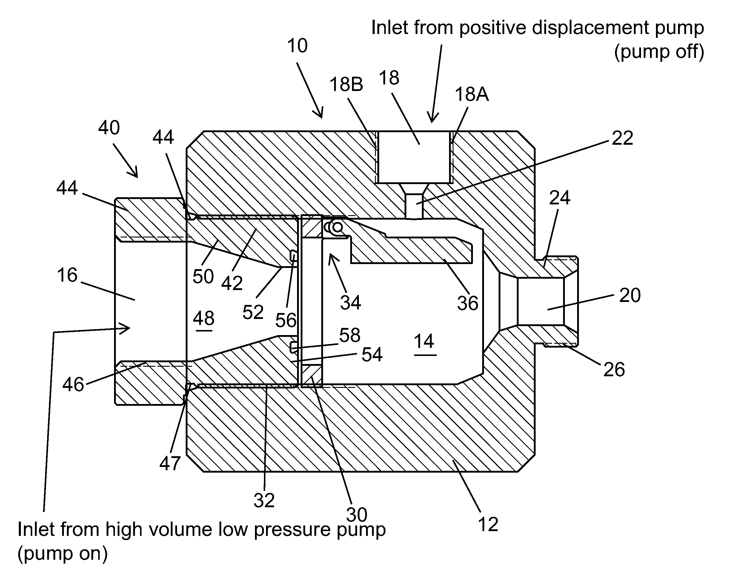
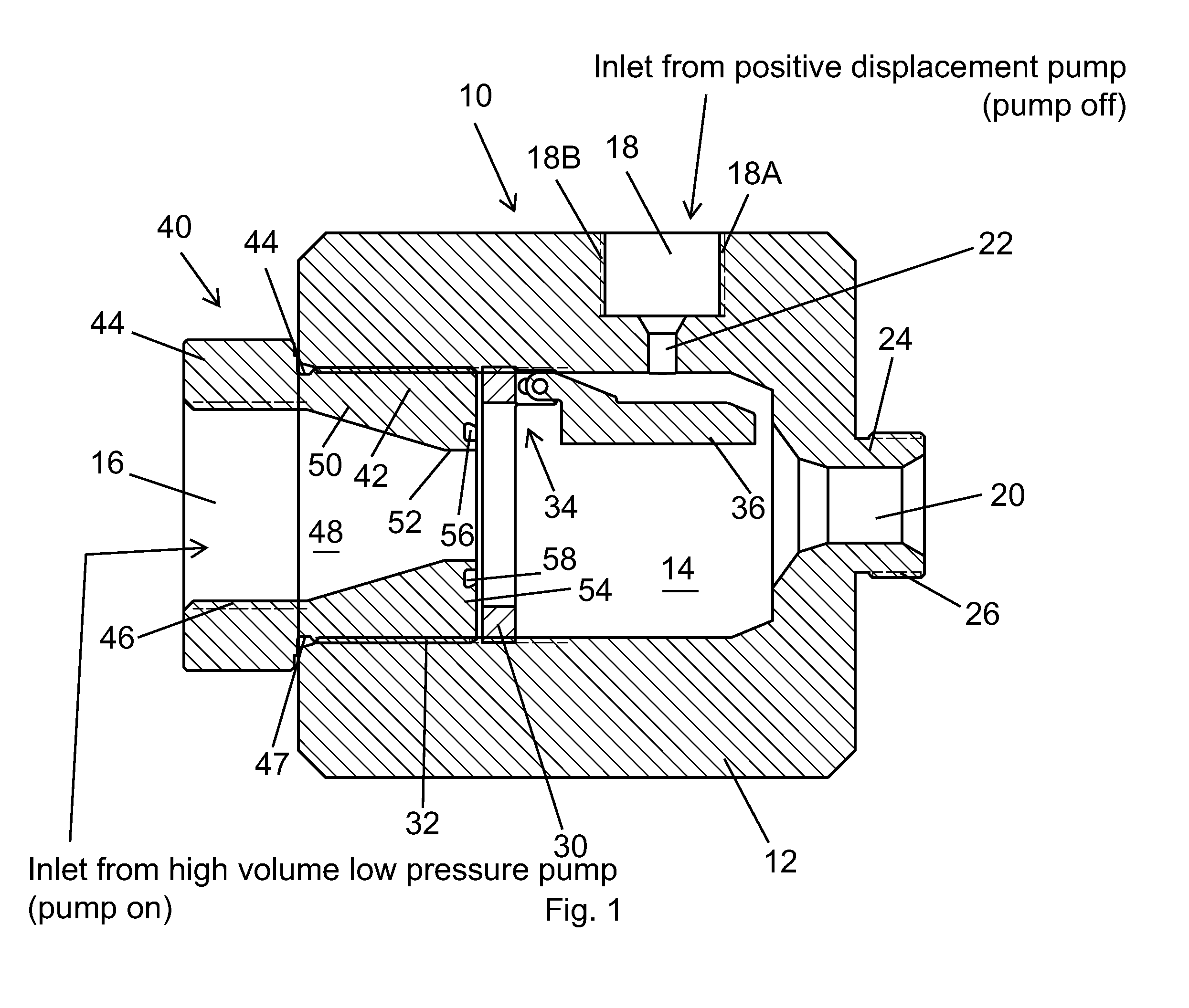
[0017]Referring first to FIG. 1, the valve shown generally as 10 comprises a valve body 12 having an internal cavity or chamber 14. The valve body 12 has a first inlet 16, a second inlet 18, and an outlet 20. Inlet 18 is counterbored and has a larger diameter section 18A with internal threads 18B and a smaller diameter section 22 opening into chamber 14. Outlet 20 is formed by a nipple 24, integral with body 12, and being e...


PUM


Abstract

A dual flow check valve having a check valve body with an interior chamber. There is a first inlet in open communication with the chamber and a second inlet in open communication with the chamber. There is also an outlet in open communication with the chamber. A pressure responsive valve element to permit one-way flow of a fluid through the first inlet into the chamber is mounted in the body.

Description

CROSS REFERENCE TO RELATED APPLICATION[0001]This application claims priority to U.S. Application No. 62 / 052,566 filed on Sep. 19, 2014, the disclosure of which is incorporated herein by reference for all purposes.FIELD OF THE INVENTION[0002]The present invention relates to check valves and, more particularly, to check valves that can be used in systems to accommodate dual flow of low and high pressure fluids.BACKGROUND OF THE INVENTION[0003]A typical check valve is a valve that only allows fluid (liquid or gas) to flow in only one direction. Prior art check valves generally are two-port valves, i.e., they have two openings in the valve body, one for fluid to enter and one for fluid to leave.[0004]There are many systems, industrial processes, and the like, wherein the flow of both high pressure and low pressure fluids are involved. A primary example of this is hydrostatic testing. A hydrostatic test is used to check pressure vessels such as pipes, pipelines, gas cylinders, boilers, e...

Claims


Application Information

Patent Timeline
Patent Type & Authority Applications(United States)
IPC IPC(8): F16K15/03F16K31/12G05D16/14
CPCF16K15/03G05D16/14F16K31/12F16K11/00
Inventor HORTON, BEN
Owner HORTON BEN
Why Eureka
Try Eureka