Inductor and power factor corrector using the same
a technology of power factor and corrector, applied in the field of power factor corrector and inductor, can solve problems such as reducing operation efficiency
- Summary
- Abstract
- Description
- Claims
- Application Information
AI Technical Summary
Benefits of technology
Problems solved by technology
Method used
Image
Examples
first embodiment
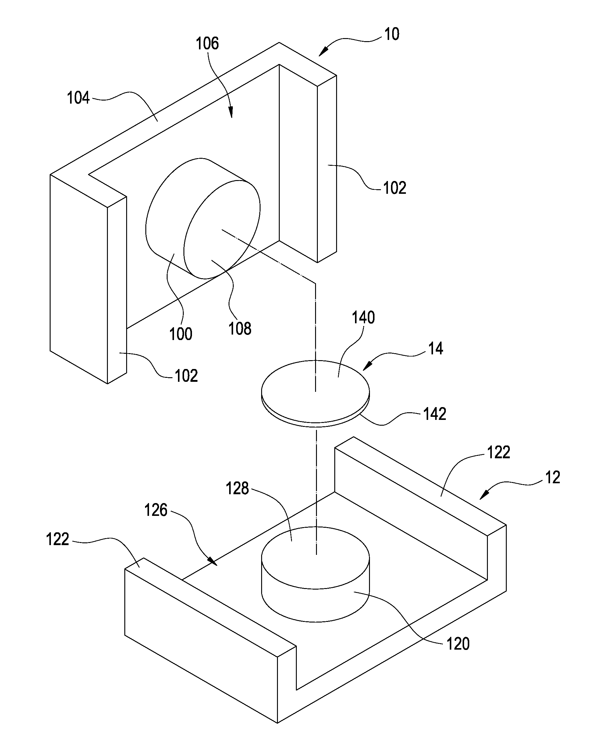
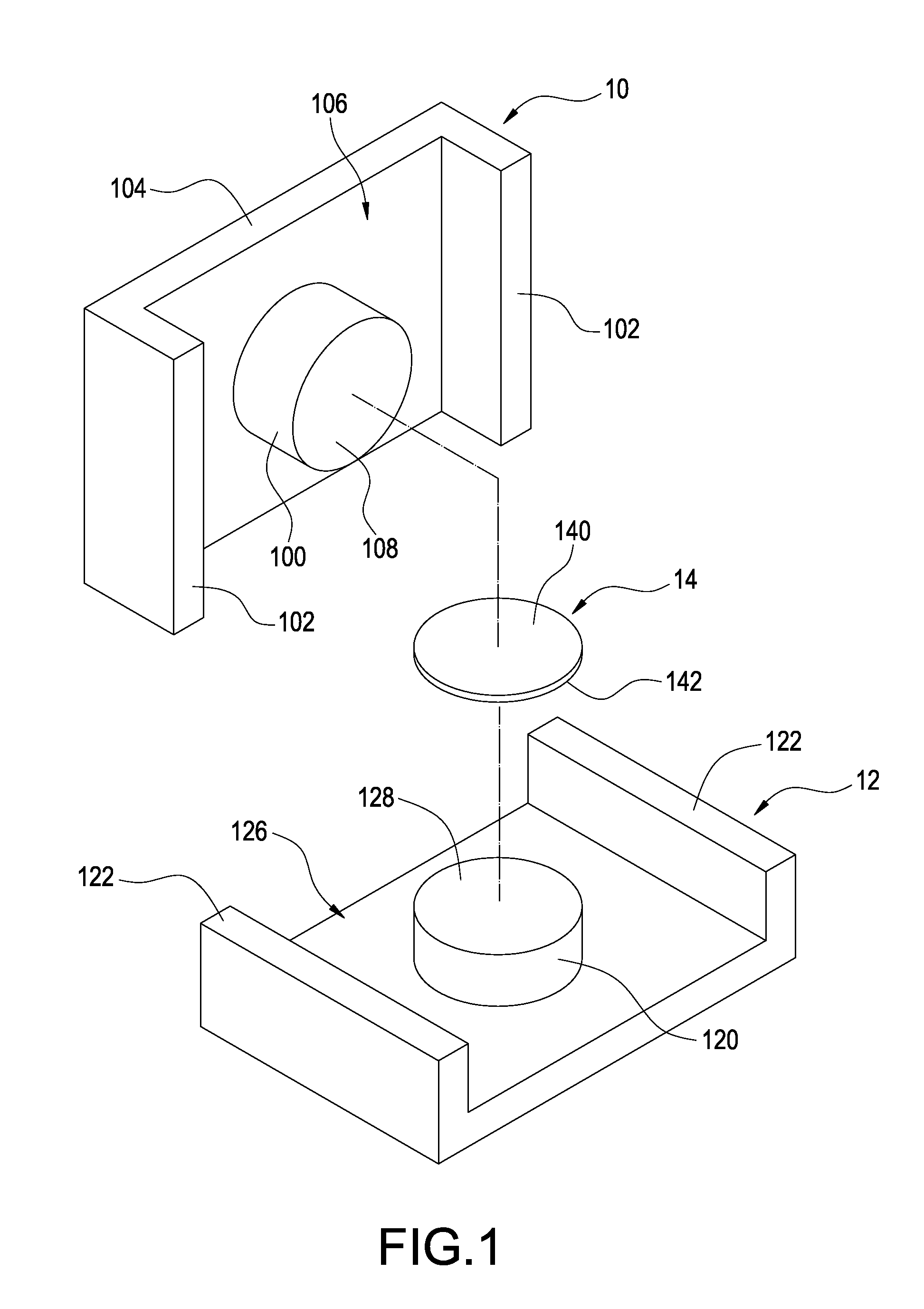
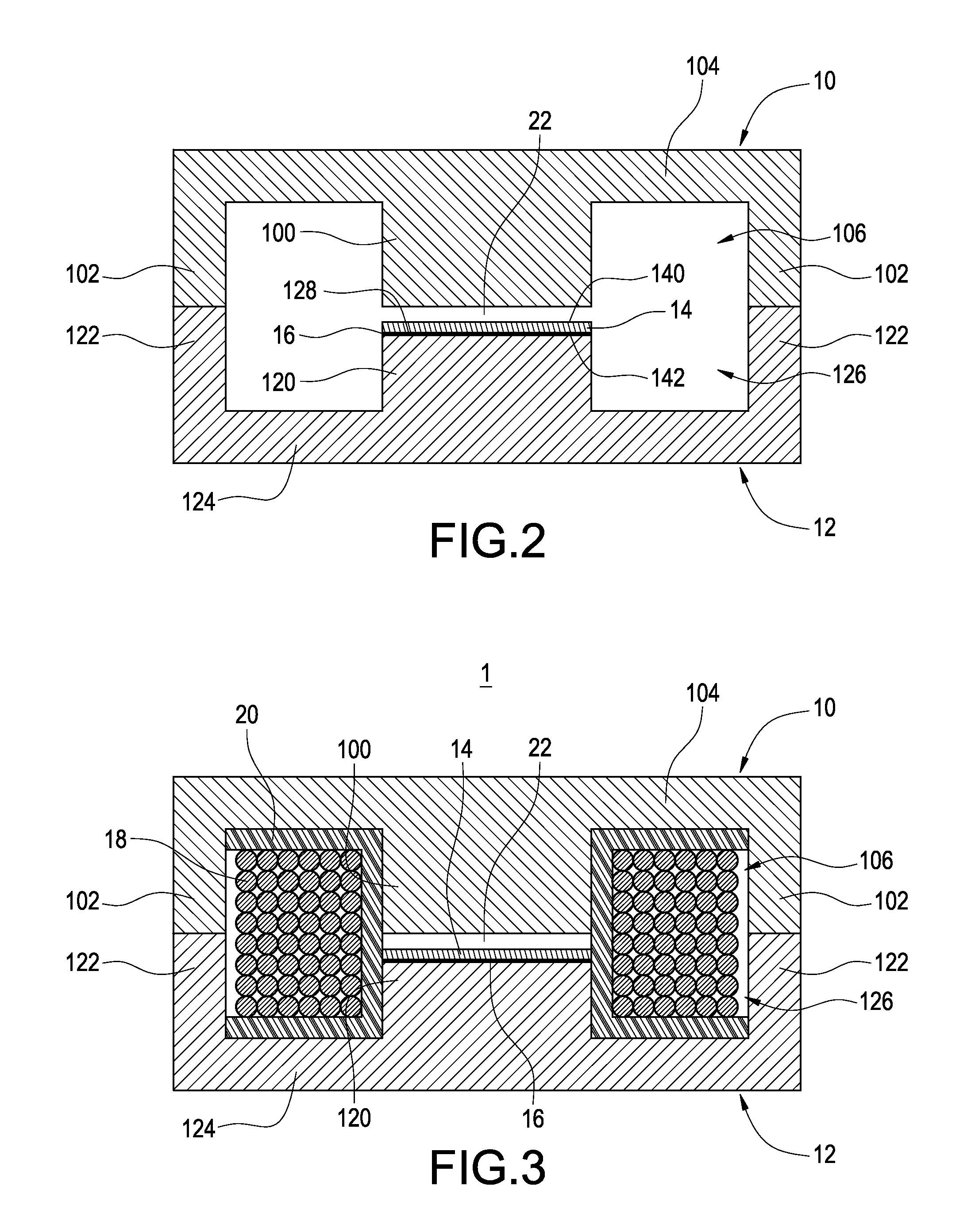
[0021]Reference is made to FIG. 1 and FIG. 2, which are respectively a perspective view and assembled view of a first magnetic core, a second magnetic core, and an auxiliary core according to the present invention. An inductor 1 of the present invention includes a first magnetic core 10, a second magnetic core 12, and an auxiliary magnetic core 14.
[0022]The first magnetic core 10 includes a first central leg 100, two first outer legs 102 arranged at two opposite sides of the first central leg 100, and a first base 104 connected to the first central leg 100 and the first outer legs 102. The first magnetic core 10 further includes first recesses 106 collectively defining by the first central leg 100, the first outer legs 102, and the first base 104, so that the first magnetic core 10 is substantially of E-shape. The first central leg 100, the first outer legs 102, and the first base 104 are respectively made of magnetic material, and the first central leg 100, the first outer legs 102...
second embodiment
[0039]FIG. 7 is a top view of an inductor according to the present invention. The inductor 1a includes a magnetic core 11, auxiliary magnetic core 13, and winding set 15. The magnetic core 11 includes a winding part 110 and two opposite end surfaces 112. In this embodiment, the magnetic core 11 is an annular magnet, and the end surfaces 112 are plane.
[0040]The permeability of the auxiliary magnetic core 13 is smaller than that of the magnetic core 11, so that the auxiliary magnetic core 13 achieves magnetic saturation earlier than that of the magnetic core 11. The auxiliary magnetic core 13 includes a top surface 130, which is substantially a plane. One of the end surfaces 112 of the auxiliary magnetic core 13 faces and is spaced from the other end surface 112, and an air gap 17 is formed therebetween. The air gap 17 is a linear air gap. The winding set 15 is wound on the winding part 110, the air gap 17, and the auxiliary magnetic core 13.
[0041]The inductor 1a, a diode, a switch, a...
PUM
 Abstract
Description
Claims
Application Information
 - R&D
- Intellectual Property
- Life Sciences
- Materials
- Tech Scout
- Unparalleled Data Quality
- Higher Quality Content
- 60% Fewer Hallucinations
Browse by: Latest US Patents, China's latest patents, Technical Efficacy Thesaurus, Application Domain, Technology Topic, Popular Technical Reports.
© 2025 PatSnap. All rights reserved.Legal|Privacy policy|Modern Slavery Act Transparency Statement|Sitemap|About US| Contact US: help@patsnap.com


