Supercharge Your Innovation With Domain-Expert AI Agents!

Manipulator and manipulator system

a manipulator and manipulator technology, applied in the field of manipulators and manipulators, can solve the problems that the area located in front of, behind or across the fold of the inner wall of the lumen in the insertion direction cannot be sufficiently treated

Active Publication Date: 2016-05-19
OLYMPUS CORP
View PDF1 Cites 2 Cited by
  • Summary
  • Abstract
  • Description
  • Claims
  • Application Information

AI Technical Summary

Benefits of technology

The present invention provides a manipulator with a distal-end joint group and a proximal-end joint group that can bend the distal-end section of an elongated insertion part in a longitudinal axis direction. The proximal-end joint group includes a plurality of proximal-end bending joints that can bend the distal-end section through 180° or more. The manipulator can be used in an endoscope system and allows for better bending and flexibility in the endoscope. The technical effects of the invention include improved maneuverability, better bending capabilities, and reduced size of the endoscope system.

Problems solved by technology

However, when used for treatment in the lumen of an organ such as the large intestine, the above endoscopes in PTLs 1 and 2 present a problem in that an affected area located in front of, behind, or across a fold on the inner wall of the lumen in the insertion direction cannot be sufficiently treated.

Method used


Image

  • Manipulator and manipulator system
  • Manipulator and manipulator system
  • Manipulator and manipulator system

Examples


Embodiment Construction

[0040]A manipulator and manipulator system according to an embodiment of the present invention will be described below with reference to the drawings.

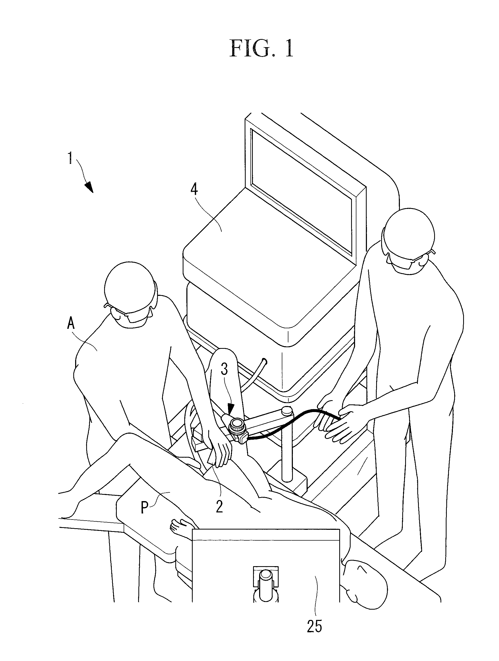
[0041]As shown in FIG. 1, the manipulator system according to this embodiment is an endoscope system 1 including a master device 2 that is manipulated by a doctor (operator) A, a slave device 3 that is driven by inputs via the master device 2, a controller 4 that controls the slave device 3 based on the inputs to the master device 2, and a monitor 25.

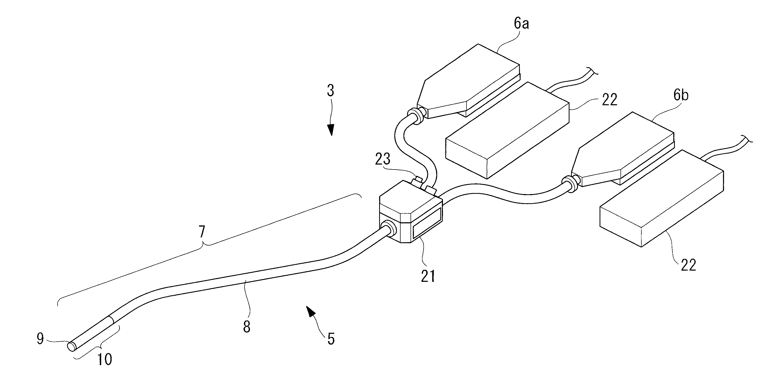
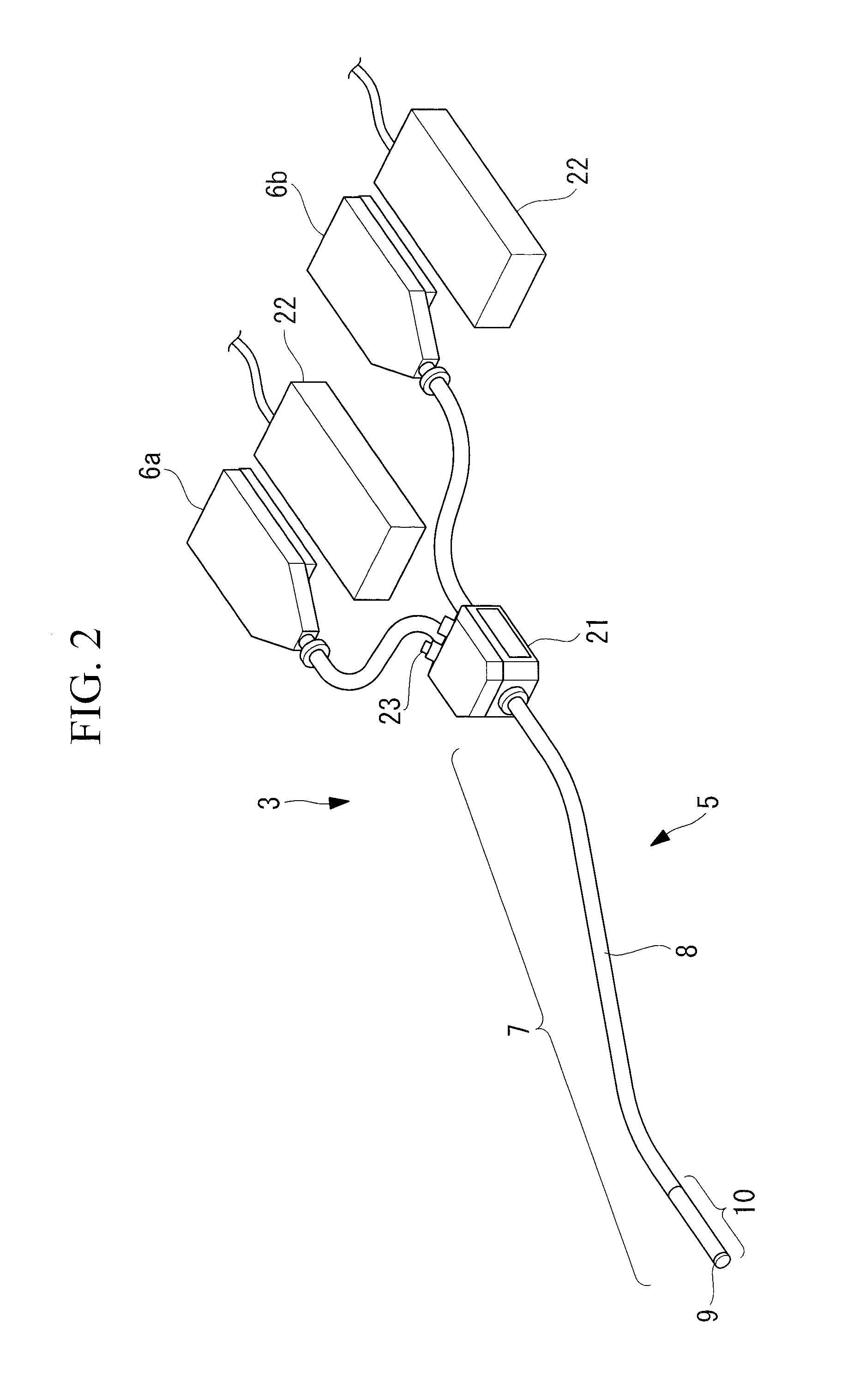
[0042]As shown in FIG. 2, the slave device 3 includes an endoscope 5 according to this embodiment for insertion into the lumen of a patient P and drive units 6a and 6b that drive the endoscope 5.

[0043]The manipulator according to this embodiment is the endoscope 5, which is a flexible endoscope including a bendable flexible elongated insertion part 7 that has an elongated flexible section 8, a tip 9 disposed at the distal end thereof, and a bending section 10 disposed between the tip 9 and...


PUM


Abstract

Provided is a manipulator including a distal-end joint group and a proximal-end joint group that are arranged adjacent to each other in a distal-end section of an insertion part in a longitudinal axis direction and that are configured to bend the distal-end section. The proximal-end joint group includes a plurality of proximal-end bending joints bendable about axes that are lined-up side-by-side to bend the distal-end section through 180° or more. The distal-end joint group includes first distal-end bending joints disposed on a distal side of the proximal-end joint group and bendable about axes crossing a plane including the axes of the proximal-end bending joints and the longitudinal axis; and a second distal-end bending joint disposed in the longitudinal axis direction relative to the axes of the first distal-end bending joints and bendable about an axis that is lined-up side-by-side with the axes of the proximal-end bending joints.

Description

CROSS-REFERENCE TO RELATED APPLICATIONS[0001]This is a continuation of International Application PCT / JP2014 / 067498, with an international filing date of Jul. 1, 2014, which is hereby incorporated by reference herein in its entirety. This application claims the benefit of Japanese Patent Application No. 2013-154468, the content of which is incorporated herein by reference.TECHNICAL FIELD[0002]The present invention relates to manipulators and manipulator systems.BACKGROUND ART[0003]There is a known endoscope including two bending sections disposed at the distal end of an insertion part and adjacent to each other in the longitudinal direction (see, for example, patent literature PTL 1 below). This endoscope allows the observation and treatment of an affected area located toward the front in the insertion direction. Also known is an endoscope having a U-shaped bend at the distal end of an insertion part (see, for example, patent literature PTL 2 below).[0004]However, when used for treat...

Claims


Application Information

Patent Timeline
IPC IPC(8): A61B34/00
CPCA61B34/72A61B1/008A61B1/0055
Inventor KISHI, KOSUKENAKAYAMA, SHINGO
Owner OLYMPUS CORP
Features
  • R&D
  • Intellectual Property
  • Life Sciences
  • Materials
  • Tech Scout
  • Unparalleled Data Quality
  • Higher Quality Content
  • 60% Fewer Hallucinations
Learn More