Positioning table

a technology of positioning table and workpiece, which is applied in the direction of control devices for conveyors, rollerways, wood feeding arangements, etc., can solve the problems of reducing energy efficiency, affecting the drive mechanism, and increasing the friction and drag on the workpi

Active Publication Date: 2016-05-26
AMS SOLUTIONS
View PDF9 Cites 28 Cited by
  • Summary
  • Abstract
  • Description
  • Claims
  • Application Information

AI Technical Summary

Benefits of technology

[0008]The present invention in one aspect includes a material handling system comprised of an array of independently controlled positioning devices, and in another aspect may be characterized as the positioning devices themselves and the method of using the system. The present invention may thus in one embodiment be a positioning table used to support and manipulate the attributes including the position, orientation, velocity and / or acceleration, of one or more workpieces such as cants, flitches, boards, trim blocks, sheets or other workpieces for transport and manipulation as better described below. The positioning devices in the array are arrayed such that no single positioning device supports multiple that is, more than one workpiece at a time thereby allowing for simultaneous and independent control of each workpiece.

Problems solved by technology

The primary drawbacks of the conventional devices are with regard to the drive mechanisms.
However, since the screw rolls also convey the work piece longitudinally, the lateral forces continue to force the work piece against the linebar, thus increasing the friction and drag on the work piece and reducing energy efficiency.
Moreover, conventional infeed devices transport and accelerate the work piece in a disorganized manner with little or no control over the forces applied to the work pieces.
This result in excessive damage to the pieces of lumber owing to the unnecessary shear forces applied to the lumber during handling.
While various diverters and re-orienteers are known in the prior art, these systems typically have not been able to perform both functions in a compact and efficient manner.

Method used


Image

  • Positioning table
  • Positioning table
  • Positioning table

Examples


Embodiment Construction

[0039]The descriptions of the workpiece positioning system employing an array of individual positioning devices, the positioning devices themselves, and the method of using the system, individually and collectively referred to herein as the invention or present invention, are intended to be read in conjunction with the accompanying drawings. The embodiments of the invention are intended to be for illustrative purposes and are not intended to limit the scope or use of other embodiments of the invention.

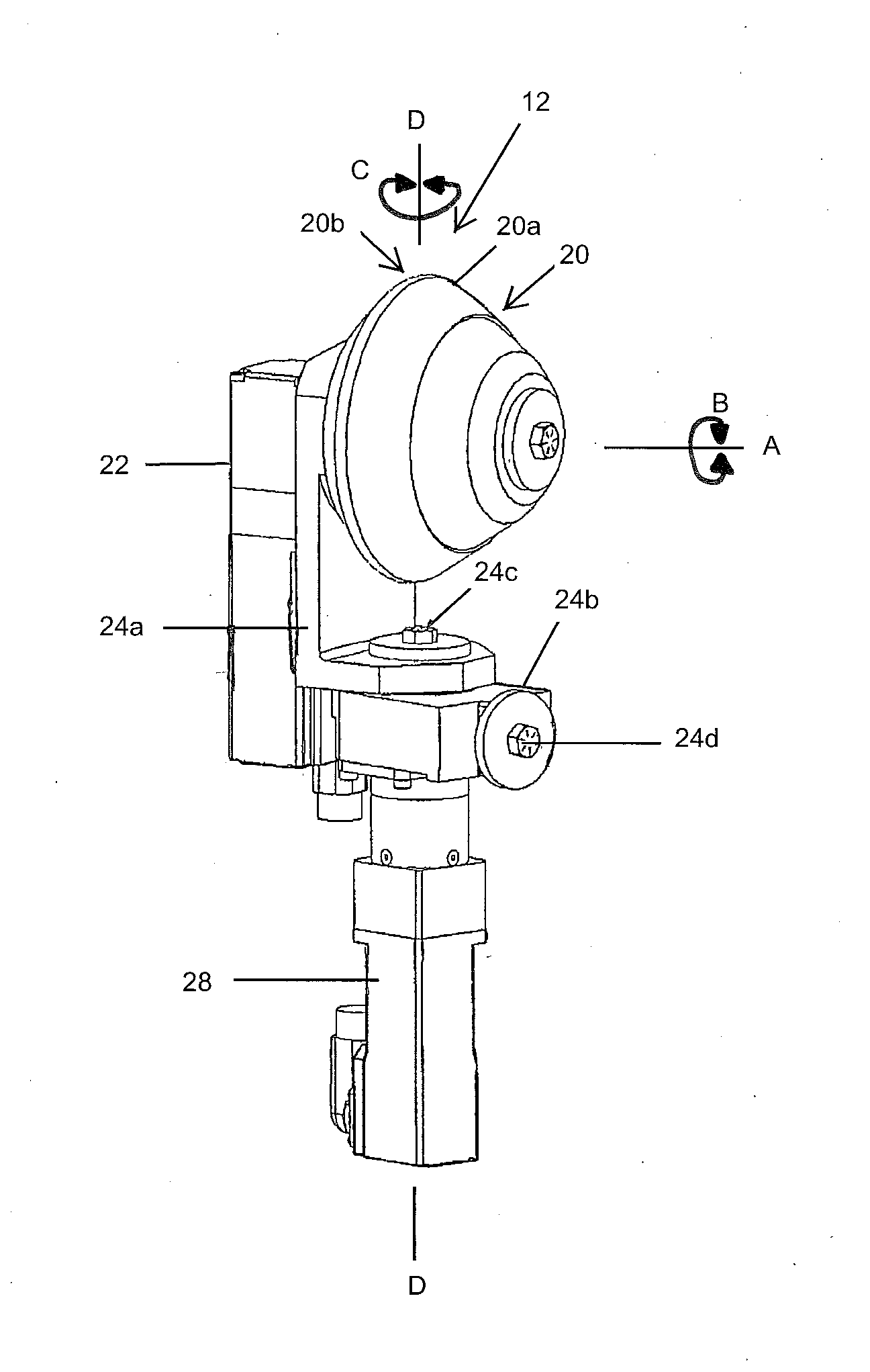
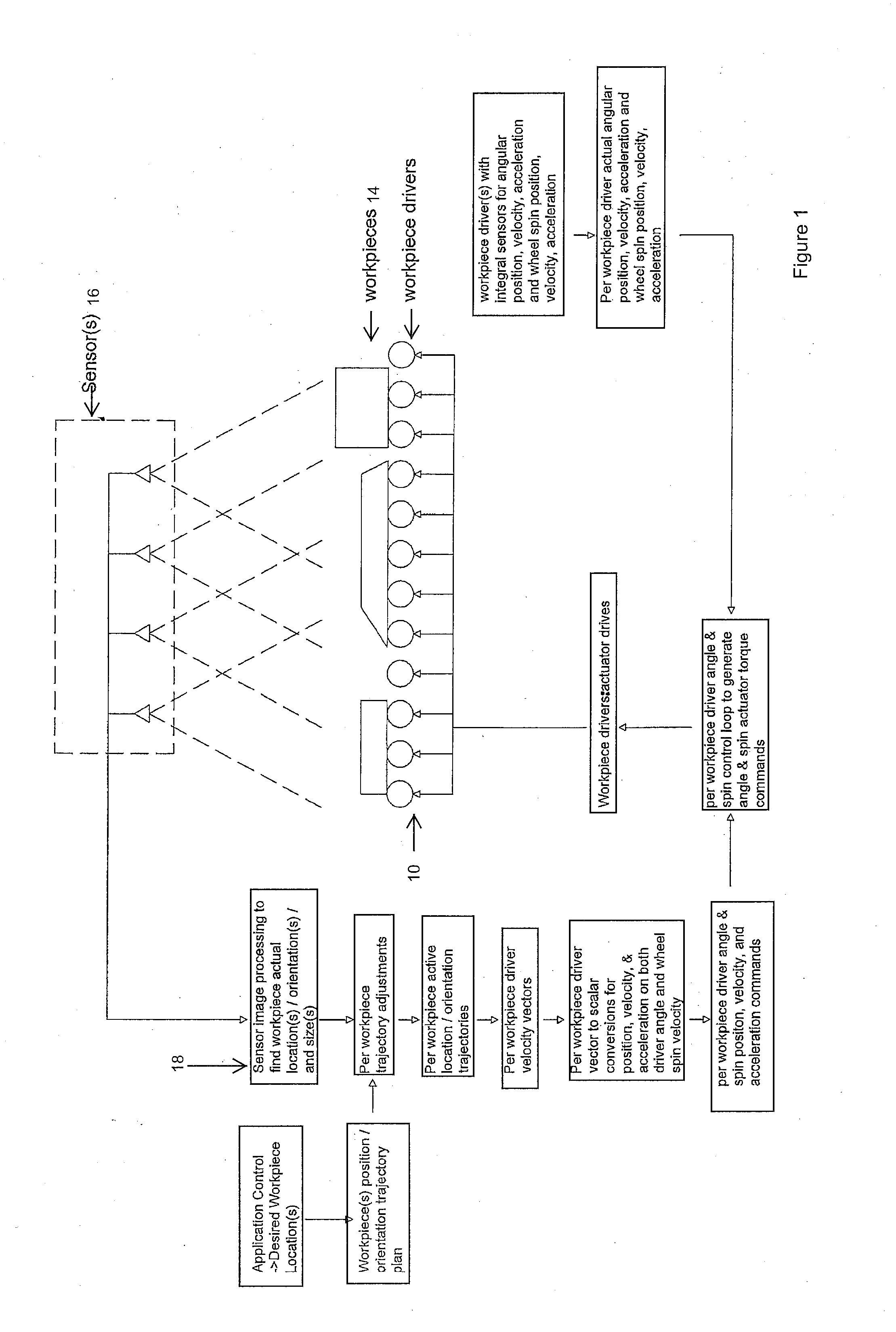
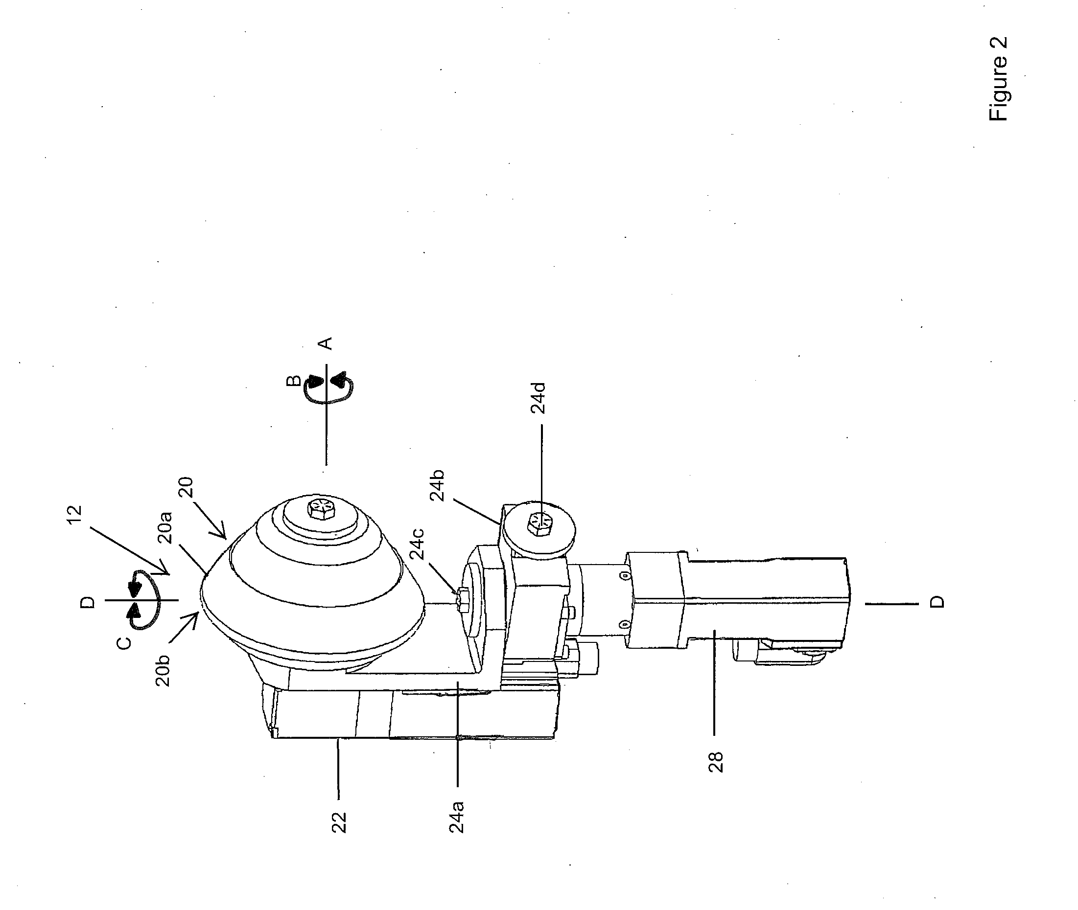
[0040]As seen in FIG. 1, a positioning table 10 includes an array of positioning devices 12. Each positioning device 12 is independently controlled by the system processor and its programmable logic controllers. Each positioning device 12 is located sufficiently close to adjacent positioning devices 12 to create a support surface, whether or not used in conjunction with a plate such as described below, that supports one or more workpieces 14 on the vertices of corresponding positioning...


PUM


Abstract

A material handling system includes an array of independently controlled positioning devices, a positioning table which support and manipulate workpiece attributes such as position, orientation, velocity and/or acceleration of workpieces on the table. The positioning devices are arrayed such that no single positioning device supports more than one workpiece at a time, thereby allowing for simultaneous and independent control of each workpiece.

Description

CROSS REFERENCE TO RELATED APPLICATIONS[0001]This application claims priority from the U.S. Provisional Patent Application No. 62 / 085,166 filed on Nov. 26, 2014, entitled: Positioning Table, and also claims priority from U.S. Provisional Patent Application No. 62 / 185,368 filed on Jun. 26, 2015, entitled: Positioning Table.FIELD OF THE INVENTION[0002]The present invention is in the technical field of material handling. More particularly, the present invention is in the technical field of piece handling in the lumber and wood industry. This invention relates to a system and apparatus for manipulating workpieces where the workpieces are positioned, transported and accelerated in order to meet downstream equipment requirements.BACKGROUND OF THE INVENTION[0003]Lumber handling, positioning tables and feeding devices are well-known in the art. The primary drawbacks of the conventional devices are with regard to the drive mechanisms. Conventional planer infeed tables utilize canted screw ro...

Claims


Application Information

Patent Timeline
Patent Type & Authority Applications(United States)
IPC IPC(8): B65G47/244B27C1/12B65G47/52
CPCB65G47/244B27C1/12B65G47/52B27C5/02B27C5/06B65G13/04B65G13/10
Inventor VETTER, RICHARD ANTHONYPOBUDA, RONALD HENRYDAVYDUKE, ROLAND WILLIAM
Owner AMS SOLUTIONS
Why Eureka
Try Eureka