
Portable Information Code Display Apparatus

a display apparatus and information code technology, applied in the direction of instruments, computing, electric digital data processing, etc., can solve the problems of operator difficulty in confirming the display state of the display screen, the display screen may not be in a reading state, and the reading apparatus is not able to read information codes

Active Publication Date: 2016-06-09
DENSO WAVE INC
View PDF3 Cites 6 Cited by
  • Summary
  • Abstract
  • Description
  • Claims
  • Application Information

AI Technical Summary

Benefits of technology

The patent text describes a display apparatus that can easily display and read information codes, even when the display is held in a difficult position. The display unit is held in a predetermined orientation that allows the reading apparatus to recognize the information code. The display can be switched to a "readable" state by changing the orientation of the display unit. This reduces delays and failures in reading the information code. The display can also be switched to a "suppressed" state to save power, but this can cause reading failure if the default screen or the application program screen is not displayed. The display can be forcibly switched to the "readable" state by changing the orientation of the display unit, and this prevents reading failure. The display can also be switched to the "suppressed" state to save power, but this may cause reading failure if the default screen or the application program screen is not displayed. Overall, this configuration improves the user experience and reduces delays and failures in reading information codes.

Problems solved by technology

In a portable display apparatus that is provided with a function for displaying an information code, the display screen may not be in a state that is suitable for reading at the timing which at an attempt is made to read the information code
As a result, the reading apparatus is not able to read the information code.
When the display screen is facing the reading apparatus side in this way, the operator has difficulty confirming the display state of the display screen.
In this way, in a configuration in which there is no guarantee that the information code will be displayed in a readable manner at the timing at which the user holds the display apparatus over the reading apparatus, problems occur in that time may be required for the information code to be successfully read after being held over the reading apparatus, and reading of the information code tends to fail.
In addition to these situations, various instances are presumed in which the display screen of the portable display apparatus enters a state in which the information code is difficult to read at the timing at which an attempt to read the information code is made.
In all of these instances, problems, such as reading delay or failure, tend to occur.
Therefore, problems, such as reading delays and failures, resulting from such situations do not easily occur.
Meanwhile, in a power saving configuration such as this, when a reading operation is performed while the display apparatus is in the suppressed state, a problem arises in that reading failure tends to occur.
Therefore, reading defects and the like resulting from the reading operation being performed while in the suppressed state do not easily occur.
Meanwhile, in a power saving configuration such as this, when a reading operation is performed in a state in which the backlight is turned OFF or the irradiation from the backlight is suppressed, recognition of the information code on the reading apparatus side becomes difficult.
A problem arises in that reading failure tends to occur.
Therefore, reading defects and the like resulting from the reading operation being performed during the backlight-OFF control or the suppression control does not easily occur.
In this case, display may be suppressed before reading by the reading apparatus is completed, and reading failure tends to occur.
In this case, reading failure tends to occur.
In particular, when the display apparatus is used in a manner in which the display unit is held such as to be oriented downward or downward at an angle in this way, the user cannot easily see the display unit during reading.
Therefore, when reading delay or failure occurs, a problem arises in that the user cannot easily identify whether the reading delay or failure has occurred as a result of display timing being off, or as a result of other factors.

Method used


Image

  • Portable Information Code Display Apparatus
  • Portable Information Code Display Apparatus
  • Portable Information Code Display Apparatus

Examples


first embodiment

[0056]A first embodiment actualizing the present invention will hereinafter be described with reference to the drawings.

Overview of a Portable Information Code Display Apparatus

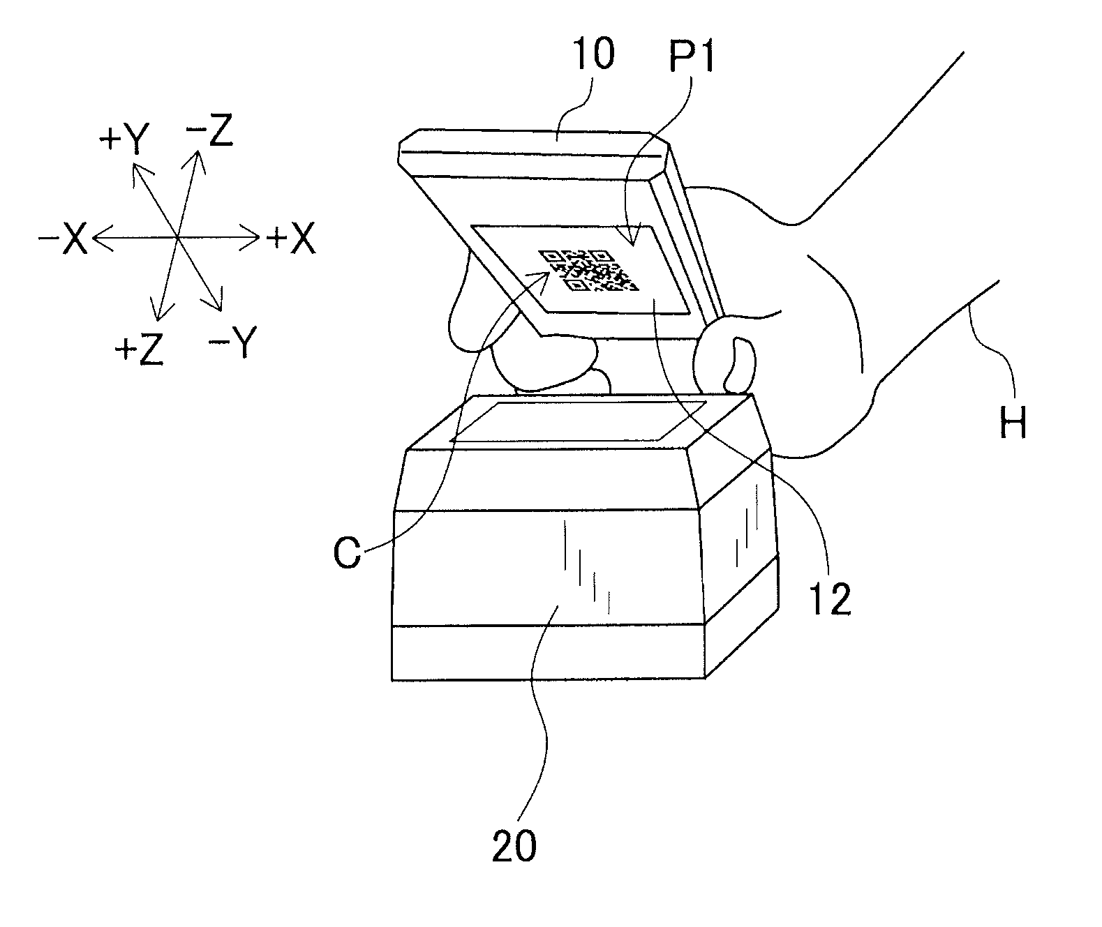
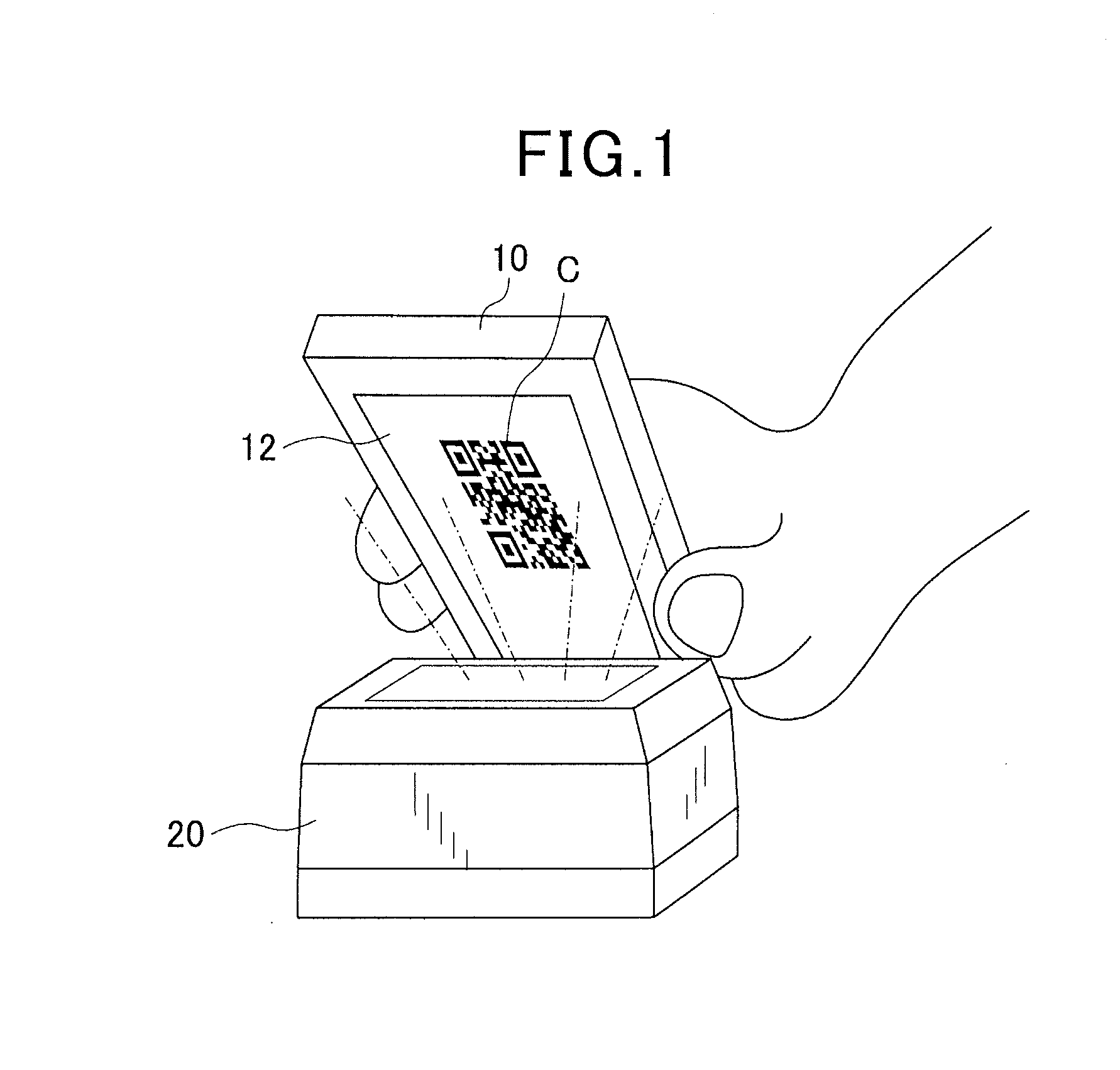
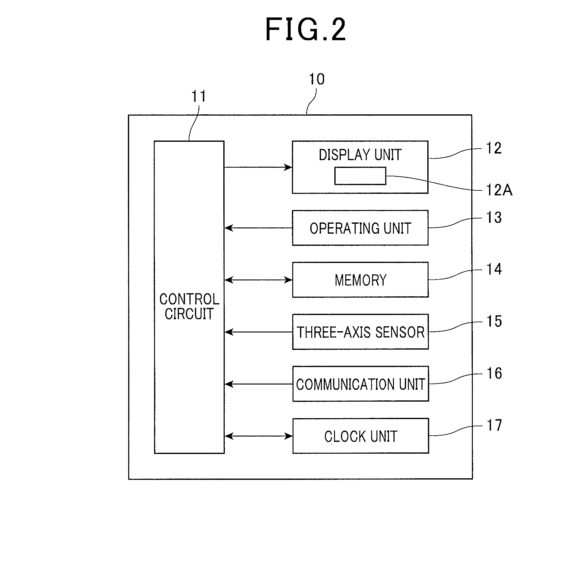
[0057]First, an overview of a portable information code display apparatus 10 will be described. The portable information code display apparatus (also referred to, hereafter, as simply a display apparatus) 10 shown in FIG. 1, FIG. 2, and the like is configured such as to be used while being gripped by a user. For example, the display apparatus 10 is configured as a portable information terminal that is carried by the user and used in various locations. The display apparatus 10 is provided with a function for generating and displaying an information code C, such as a barcode or a two-dimensional code. The display apparatus 10 is merely required to be a portable information apparatus that has a display, such as a mobile phone, a smartphone, or a wearable terminal. Functions of the display apparatus 10, other tha...

second embodiment

[0116]A second embodiment differs from the first embodiment only in that the code display process in FIG. 9 is changed as in FIG. 10. The second embodiment is similar to the first embodiment in other aspects. In the process in FIG. 10, the processes at S21 to S23 are respectively the same as the processes at S1 to S3 in FIG. 9. Therefore, detailed descriptions of these processes are omitted.

[0117]In the process in FIG. 10, the process at S24 is performed instead of the process at S4 in FIG. 9. That is, after determining that a predetermined amount of time has elapsed at S23 (that is, after the information code C has been displayed over a predetermined amount of time in the readable state as in FIG. 8), in the process at S24, the display apparatus 10 performs a process to switch the display to a display screen for an application program. The display screen displayed in the process at S24 is, for example, the display screen of the application program displayed immediately before the p...

third embodiment

[0119]Next, a third embodiment will be described. The hardware configuration of the display apparatus 10 according to the third embodiment is the same as that according to the first embodiment. Therefore, a detailed description of the hardware configuration will be omitted. According to the third embodiment, a display such as that shown in FIG. 11, for example, can be performed by any of the application programs present in the display apparatus 10.

[0120]In this configuration, the user performs a predetermined operation on the operating unit 12 and starts a predetermined application program. As a result, an image display such as that in FIG. 11 is started. When the image display is started, a plurality of images are successively displayed on the display unit 12, as shown in the left-hand drawing in FIG. 11. For example, in the example in FIG. 11, an image P1 of the information code C, an image P2 including characters indicating the name of an airline company, and an image P3 includin...


PUM


Abstract

There is provided a portable information code display apparatus. The apparatus includes a display unit that is capable of displaying an image in addition to a direction detecting unit and a display control unit. The direction detecting unit is capable of detecting that the display unit is oriented is a predetermined orientation. The display control unit controlling display performed in the display unit. Practically, the display control unit displays an information code on the display unit in a predetermined readable state in which the information is readable and to maintains the display of the information code in the readable state, when the direction detecting unit detects that the display unit is oriented in the predetermined orientation.

Description

CROSS-REFERENCE TO RELATED APPLICATIONS[0001]This application is based on and claims the benefit of priority from earlier Japanese Patent Applications No. 2014-247160 filed Dec. 5, 2014 and No. 2015-217302 filed Nov. 5, 2015, the descriptions of which are incorporated herein by reference.BACKGROUND[0002]1. Technical Field[0003]The present invention relates to an apparatus on which an information code is displayed, and in particular, to a portable information code display apparatus.[0004]2. Related Art[0005]Information codes are being used in increasingly wider applications over the recent years. For example, information codes are also being used in such a manner that the information code is displayed on a portable terminal, such as a tablet terminal or a smartphone, in addition to media such as paper, and read by another apparatus. A technique such as that in JP-A-2009-271553, for example, has been proposed as a technique for using an information code displayed on a display apparatu...

Claims


Application Information

Patent Timeline
Patent Type & Authority Applications(United States)
IPC IPC(8): G09G5/36G06F3/041
CPCG06F3/0412G09G5/36G06F3/147G09G3/3406G09G2330/021G09G2340/0492G09G2380/04
Inventor USHIJIMA, TAKAO
Owner DENSO WAVE INC
Learn More