Energy-harvesting device

a technology of energy harvesting and energy storage, which is applied in piezoelectric/electrostriction/magnetostriction machines, instruments, electrical equipment, etc., can solve the problems of unstable electricity generated by energy harvesting and difficulty in keeping a constant level

Inactive Publication Date: 2016-06-16
PANASONIC INTELLECTUAL PROPERTY MANAGEMENT CO LTD
View PDF3 Cites 65 Cited by
  • Summary
  • Abstract
  • Description
  • Claims
  • Application Information

AI Technical Summary

Benefits of technology

[0006]An energy-harvesting device includes a power generating element configured to generate electric power, a storage capacitor configured to store the electric power generated by the power generating element, a DC / DC converter configured to convert, into a predetermined voltage, a voltage obtained from the electric power generated by the power generating element and the electric power stored in the storage capacitor, a delay section for delaying a voltage corresponding to a voltage across the storage capacitor, and a controller configured to output an activating signal that activates the DC / DC converter when the delayed voltage is higher than a reference voltage. This device activates the DC / DC converter after the storage capacitor is sufficiently charged, thereby providing a predetermined output voltage and power. The energy-harvesting device thus can produce a necessary voltage and power.

Problems solved by technology

However, since the electric power generated by the energy harvesting is unstable and difficult to keep a constant level, the AC current is rectified and converted to a direct-current (DC) current by rectifying circuit 502, and then, the converted electric power is charged in storage capacitor 503.

Method used


Image

  • Energy-harvesting device
  • Energy-harvesting device
  • Energy-harvesting device

Examples


exemplary embodiment 1

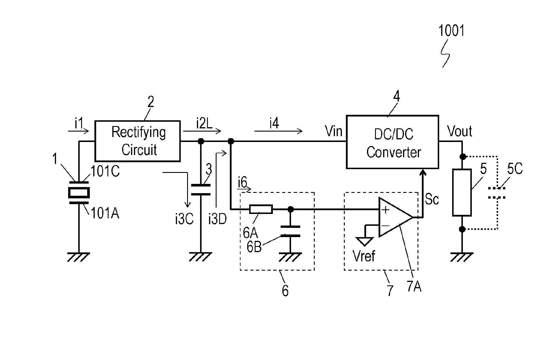
[0017]FIG. 1 is a circuit diagram of energy-harvesting device 1001 in accordance with Exemplary Embodiment 1. Energy-harvesting device 1001 includes power generating element 1 configures to generate electric power, rectifying circuit 2 connected to power generating element 1, storage capacitor 3 connected to rectifying circuit 2 configured to store direct-current (DC) power rectified by rectifying circuit 2, DC / DC converter 4 connected to rectifying circuit 2 and storage capacitor 3 and configured to convert DC voltage Vin rectified by rectifying circuit 2 to a predetermined DC voltage Vout, delay section 6 connected to rectifying circuit 2, storage capacitor 3, and an input terminal of DC / DC converter 4 configured to receive a voltage corresponding to a voltage of storage capacitor 3, and controller 7 configured to output, based on a voltage supplied from delay section 6, activating signal Sc which activates DC / DC converter 4.

[0018]The voltage across storage capacitor 3 is divided,...

exemplary embodiment 2

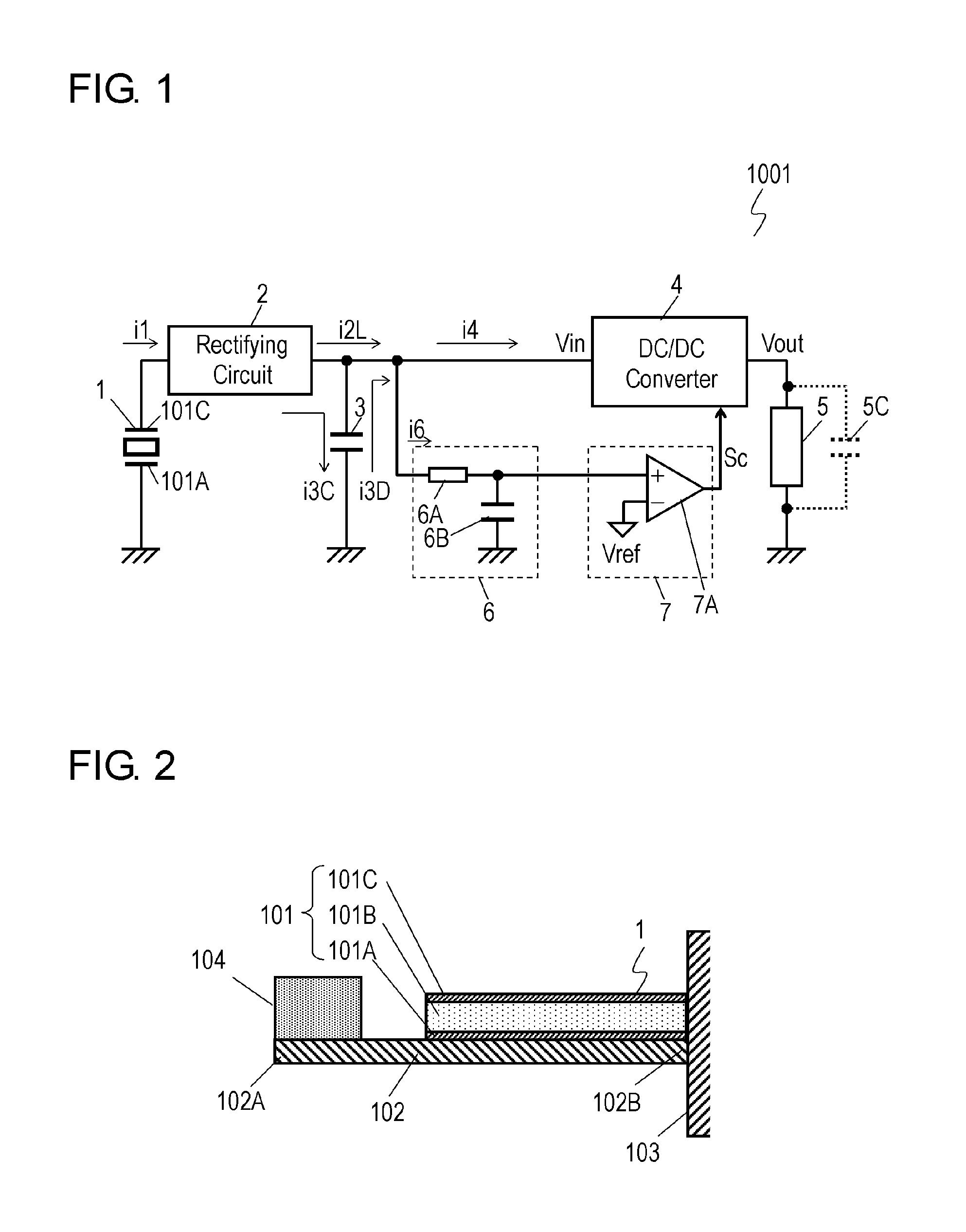
[0046]FIG. 8 is a circuit diagram of energy-harvesting device 1002 in accordance with Exemplary Embodiment 2. In FIG. 8, components identical to those of energy-harvesting device 1001 shown in FIG. 1 in accordance with Embodiment 1 are denoted by the same reference numerals. Energy-harvesting device 1002 includes controller 107 instead of controller 7 of energy-harvesting device 1001 shown in FIG. 1 in accordance with Embodiment 1.

[0047]Controller 107 includes CMOS inverter 107A that receives a voltage delayed by delay section 6 and then outputs activating signal Sc. To be more specific, while voltage Vin is applied, and when the voltage delayed by delay section 6 exceeds a threshold of CMOS inverter 107A, inverter 107A starts working. Inverter 107A can be designed such that the threshold can be independent of a voltage input to inverter 107A.

[0048]Similarly to energy-harvesting device 1001 shown in FIGS. 1 to 5 in accordance with Embodiment 1, energy-harvesting device 1002 in accor...


PUM


Abstract

An energy-harvesting device includes a power generating element configured to generate electric power, a storage capacitor configured to store the electric power generated by the power generating element, a DC/DC converter configured to convert, into a predetermined voltage, a voltage obtained from the electric power generated by the power generating element and the electric power stored in the storage capacitor, a delay section for delaying a voltage corresponding to a voltage across the storage capacitor, and a controller configured to output an activating signal that activates the DC/DC converter when the delayed voltage is higher than a reference voltage. The energy-harvesting device thus can produce a necessary voltage and power.

Description

TECHNICAL FIELD[0001]The present invention relates to an energy-harvesting device using a power generating element.BACKGROUND ART[0002]An energy harvesting utilizing light energy, heat energy, or kinetic energy such as vibrations and a pressure for generating electric power has been paid in attention. Electronic devices driven by an energy-harvesting device that uses the foregoing power generation have been developed. These electronic devices include sensors or transmitters requiring no maintenance, such as replacing of batteries.[0003]FIG. 10 is a block diagram of conventional energy-harvesting device 500. In the case that power generating element 501 used for the energy harvesting is an element that generates electric power due to vibration, power generating element 501 generates positive and negative electric charges alternately in response to the vibration, and generates an alternating-current (AC) current by taking out the electric charges. However, since the electric power gen...

Claims


Application Information

Patent Timeline
Patent Type & Authority Applications(United States)
IPC IPC(8): H02J1/06
CPCH02J1/06H02N2/181H10N30/306
Inventor TAMURA, MASAYAKATSUMURA, HIDENORI
Owner PANASONIC INTELLECTUAL PROPERTY MANAGEMENT CO LTD
Why Eureka
Try Eureka