Vacuum Insulation Body

a technology of vacuum insulation and body, applied in the field of vacuum insulation body, can solve the problems of reducing the effectiveness of heat insulation body and involving a relatively high apparatus expenditure, and achieve the effect of evacuating particularly easily and efficiently

Active Publication Date: 2016-06-23
LIEBHERR HAUSGERATE LIENZ +1
View PDF2 Cites 43 Cited by
  • Summary
  • Abstract
  • Description
  • Claims
  • Application Information

AI Technical Summary

Benefits of technology

[0009]It is the object underlying the present invention to develop a vacuum insulation body as mentioned above to the effect that the same can be evacuated particularly easily and efficiently. This object is solved by a vacuum insulation body with the features claimed. Accordingly, it is provided that the adsorbent material partly or completely is arranged in the region of said opening.

Problems solved by technology

Such introduction of gas or such increase of the gas pressure increases the thermal conductivity and thus reduces the effectiveness of the heat insulation body.
It is known from the prior art to perform the vacuum generation in the vacuum insulation body in a vacuum chamber, which involves a comparatively high expenditure of apparatus.

Method used


Image

  • Vacuum Insulation Body
  • Vacuum Insulation Body

Examples


Embodiment Construction

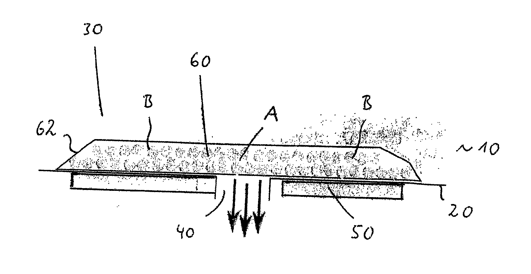
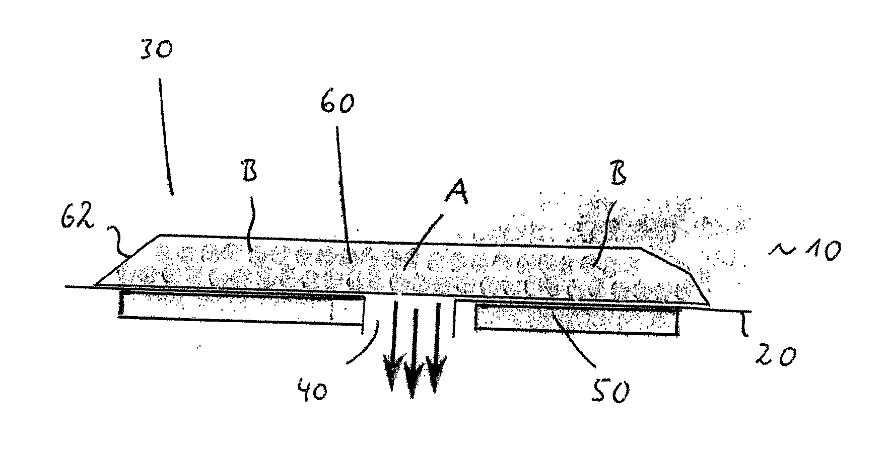
[0041]In FIG. 1, a partial region of a vacuum insulation body according to the invention is designated with the reference numeral 10.

[0042]This vacuum insulation body includes a vacuum-tight film or a high-barrier film 20 as well as a core material 30, which can be a bed, such as for example pearlite.

[0043]Reference numeral 40 designates an opening or an evacuation portion which during the evacuation process is connected with a non-illustrated vacuum pump, so that according to the direction of the arrow a flow is generated from the vacuum region and the vacuum thus is generated.

[0044]As is furthermore shown in FIG. 1, in the region (in the illustrated flow direction during evacuation) directly before the opening 40 in the vacuum region an adsorbent material 60 is located, such as a drier / getter, e.g. zeolite, which is arranged not only in the region which is in alignment with the opening 40, but also in the regions adjacent thereto. In FIG. 1, the aligned region is designated with t...


PUM


Abstract

A vacuum insulation body includes at least one vacuum-tight casing and at least one vacuum region surrounded by the casing. The casing is provided with at least one opening, in particular with at least one evacuation port, for evacuating the vacuum region. At least one adsorbent material is present in the vacuum insulation body. The adsorbent material is partly or completely arranged in the region of the opening.

Description

BACKGROUND OF THE INVENTION[0001]The present invention relates to a vacuum insulation body with at least one vacuum-tight casing and with at least one vacuum region which is surrounded by the casing, wherein the casing is provided with at least one opening, in particular with at least one evacuation port, for evacuating the vacuum region, and wherein at least one adsorbent material is present in the vacuum insulation body.[0002]From the prior art it is known to use vacuum insulation bodies for the heat insulation of refrigerators and freezers, which are present in the region between the outer shell of the appliance and the inner container or the inside of the door.[0003]Such vacuum insulation bodies comprise a vacuum-tight casing and at least one vacuum region surrounded by the casing, in which a supporting or core material is present which provides the vacuum insulation body with the required mechanical stability and which in addition prevents that the sides of the casing rest agai...

Claims


Application Information

Patent Timeline
Patent Type & Authority Applications(United States)
IPC IPC(8): F25D23/06F27B5/04
CPCF25D23/061F25D2201/14F27B5/04F25D23/062F25D23/06F16L59/065Y10T428/231
Inventor HIEMEYER, JOCHENFREITAG, MICHAELKERSTNER, MARTIN
Owner LIEBHERR HAUSGERATE LIENZ
Why Eureka
Try Eureka