
Calendar display device for a timepiece

a display device and timepiece technology, applied in mechanical time indication, instruments, visual indications, etc., can solve the problems of occupying too much space on the plate, affecting the reliability of gearing, and the maximum size of characters that can be displayed consequently remains very limited, so as to improve the balance of indications, improve the reliability of each indexing, and increase the compactness

Active Publication Date: 2016-06-30
ETA SA MFG HORLOGERE SUISSE
View PDF7 Cites 1 Cited by
  • Summary
  • Abstract
  • Description
  • Claims
  • Application Information

AI Technical Summary

Benefits of technology

The present invention improves the balance of indications on the two wheels by moving some of the units indications to a modified tens disc. This results in better alignment of characters for a combined display. Additionally, the minimum sequence of indications on the modified tens disc is increased, making it easier and more reliable to index. The two display discs are formed by rotating elements of annular shape, which allows for a smaller display that can be placed in a compact space. This invention is advantageous for improved control mechanism placement and overall design.

Problems solved by technology

One drawback of this type of calendar mechanism is that it requires a very large number of parts, which are separate for the control and display mechanism, and therefore occupy too much space on the plate.
Further, the cross associated with the tens disc has a very small number of teeth, which is detrimental to gearing reliability due to the large angular steps required during each indexing operation.
The fact that the modified tens disc bears a larger number of symbols certainly facilitates the gearing mechanism, but because the sequence of indications relating to the units is arranged on a disc integral in rotation with a programme wheel having 31 sectors, the maximum size of the characters that can be displayed consequently still remains very limited.

Method used


Image

  • Calendar display device for a timepiece
  • Calendar display device for a timepiece
  • Calendar display device for a timepiece

Examples


Embodiment Construction

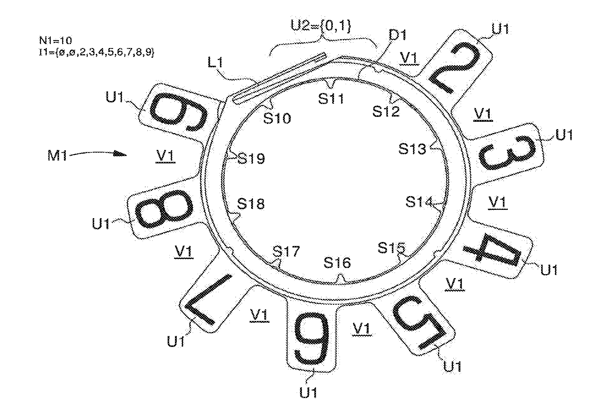
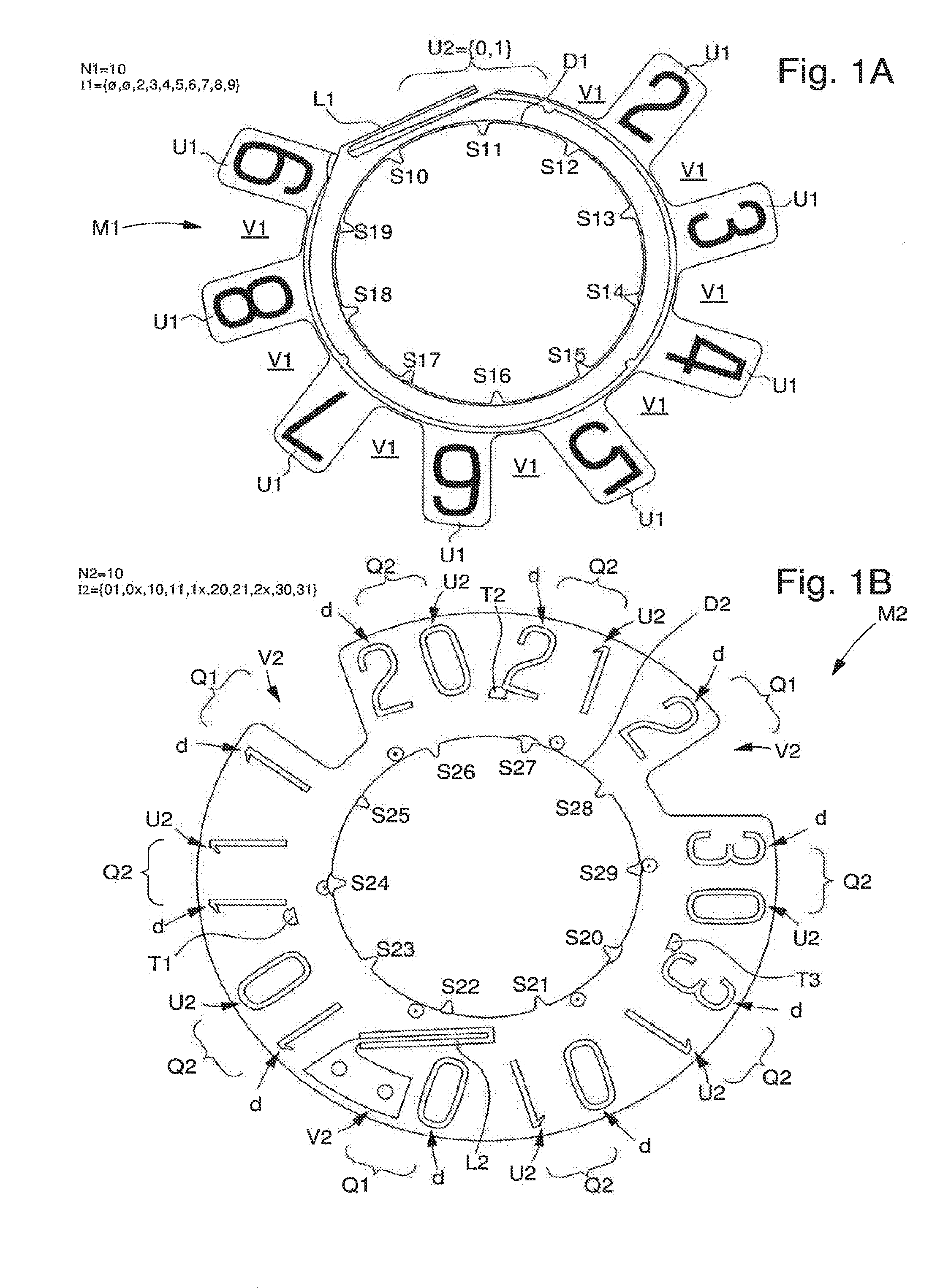
[0024]FIGS. 1A and 1B respectively illustrate two discs used for the grand date display according to a preferred embodiment of the invention.

[0025]The first disc M1 of FIG. 1A consists of a units disc provided in a conventional manner with 10 display segments respectively referenced S10, S11, S12, S13, S14, S15, S16, S17, S18 and S19, regularly spaced at the periphery of first disc M1, each corresponding to one of the numerals of the series from 0-9 but in which certain numbers have been truncated, here the numbers {0, 1}. The first disc M1 therefore bears a first series of symbols I1 which consists of a first space, a second space, followed by a first sequence U1 of first units numerals u1={2,3,4,5,6,7,8,9}. The first series of symbols I1={Ø, Ø, 2-9} thus contains ten display symbols, including 8 units numerals 2-9 and the two spaces Ø correspond to a second sequence U2 of second units numerals u2, here the numeral 0 and the numeral 1, the display of which is moved to a second seri...


PUM


Abstract

Grand date calendar display device for a watch movement comprising a first disc and a second disc, arranged to display, on certain dates, first date values by combining symbols borne by said first disc and symbols borne by said second disc, and on other dates, second date values by symbols borne only by said second disc. The first disc is a modified units display disc, bearing a first series of symbols comprising a first sequence of at most nine first consecutive units numerals truncated by at least a second units numeral with respect to the complete series of ten units, and the second disc is a modified tens display disc including a second series of symbols for the display of at least the tens of the date, comprising at least one combination of two numerals formed of a tens numeral and a second units numeral.

Description

[0001]This application claims priority from European Patent Application No. 14200609.7 filed Dec. 30, 2014, the entire disclosure of which is hereby incorporated herein by reference.FIELD OF THE INVENTION[0002]The present invention concerns a calendar display mechanism, and in particular a “grand date” calendar display mechanism.BACKGROUND OF THE INVENTION[0003]Conventional calendar display devices for timepieces, and in particular wearable wristwatches, usually use an annular date-disc including 31 regularly distributed annular sectors, each of the sectors including an indication corresponding to one of possible dates of the month. The date-disc is indexed one position every day, so as to reveal through an aperture the date value corresponding to each day, which is formed of one or more numerals. The angular sector occupied by each indexing position is thus relatively limited (360 / 31 i.e. slightly less than 12 degrees), which greatly restricts the maximum size of the numbers that c...

Claims


Application Information

Patent Timeline
Patent Type & Authority Applications(United States)
IPC IPC(8): G04B19/247
CPCG04B19/247G09D3/00G04B19/253
Inventor ROMBACH, STEFAN
Owner ETA SA MFG HORLOGERE SUISSE
Learn More