Pushcart

a pushcart and holding portion technology, applied in the field of pushcarts, can solve the problems of poor application of conventional techniques and poor user-operability of pushcarts, and achieve the effect of shortening the movement distance of the holding portion and improving user-operability

Inactive Publication Date: 2016-08-04
MURATA MFG CO LTD
View PDF0 Cites 6 Cited by
  • Summary
  • Abstract
  • Description
  • Claims
  • Application Information

AI Technical Summary

Benefits of technology

[0018]Accordingly, the movement distance L2·sin θ of the holding portion of the pushcart of the present disclosure is shorter than the movement distance L1·sin θ of the holding portion 816 of the pushcart 800 assuming the application of the conventional technique. As such, when a user holds the holding portion and moves the pushcart of the present disclosure, it is sufficient for the user to push the holdi

Problems solved by technology

This raises a problem that user-operability of the pushcart 800 a

Method used


Image

  • Pushcart
  • Pushcart
  • Pushcart

Examples


first embodiment

[0046]Hereinafter, a pushcart 100 according to the present disclosure will be described.

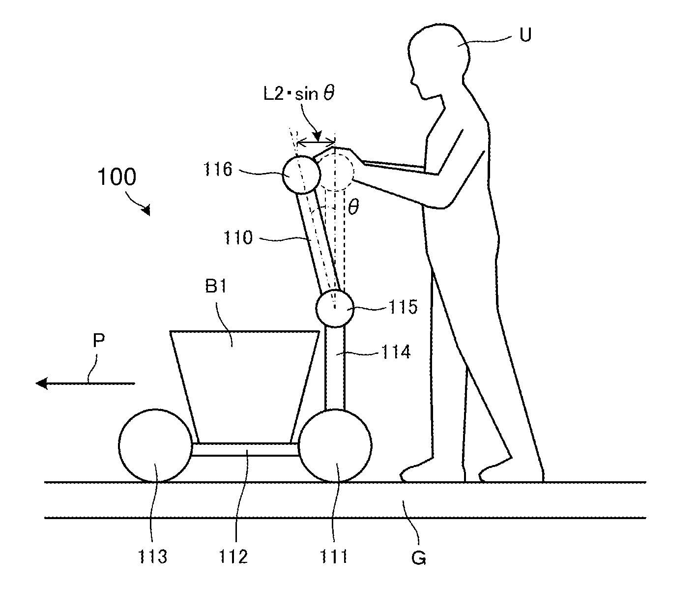
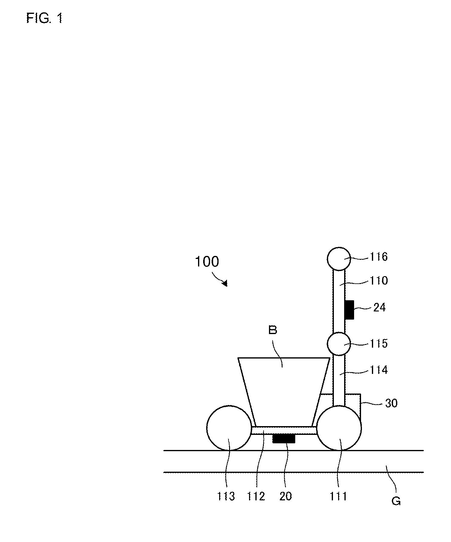
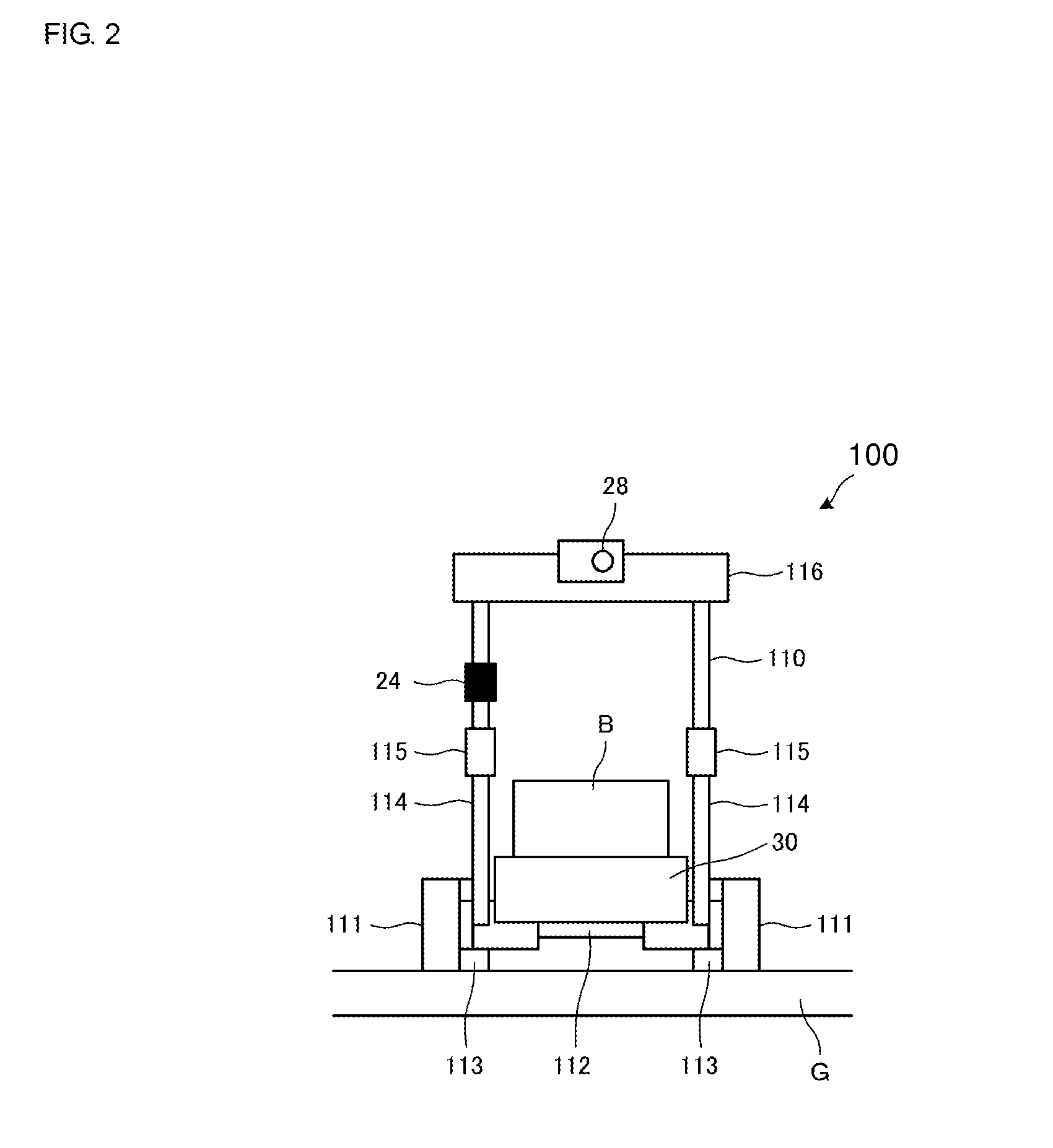
[0047]FIG. 1 is a schematic side view of the pushcart 100 according to the first embodiment of the present disclosure. FIG. 2 is a schematic rear view of the pushcart 100 shown in FIG. 1. FIGS. 3A and 3B include schematic side views of the pushcart 100 shown in FIG. 1 when a user U moves the pushcart 100.

[0048]The pushcart 100 includes, as shown in FIGS. 1 and 2, a steering unit 110, a main wheel 111, a dolly portion 112, an auxiliary wheel 113, a connecting unit 114, a slope angle sensor 20, a gyrosensor 24, and a case 30. The pushcart 100 is used as a shopping cart, a baby carriage, or a walking assistant cart, for example.

[0049]The dolly portion 112 corresponds to “base unit” of the present disclosure. The gyrosensor 24 corresponds to “angle change detector” of the present disclosure. The slope angle sensor 20 corresponds to “slope angle detector” of the present disclosure.

[0050]Note that, in ...

second embodiment

[0091]Hereinafter, a pushcart 200 according to the present disclosure will be described.

[0092]FIG. 5 is a schematic side view of the pushcart 200 according to the second embodiment of the present disclosure.

[0093]The pushcart 200 of the second embodiment differs from the pushcart 100 of the first embodiment in a point that a supporter 212 is included therein in place of the dolly portion 112. The supporter 212 is formed in a rectangular frame shape, and the pair of auxiliary wheels 113 opposing to each other is supported by the supporter 212 in a rotatable manner. The connecting unit 114 is connected to an end of the supporter 212 on the opposite side to the auxiliary wheels 113. In the pushcart 200, the supporter 212 corresponds to “base unit” of the present disclosure. The pushcart 200 is used as a baby carriage, for example. Since other constituent elements are the same as those of the pushcart 100, descriptions thereof are omitted herein.

third embodiment

[0094]Hereinafter, a pushcart 300 according to the present disclosure will be described.

[0095]FIG. 6 is a schematic side view of the pushcart 300 according to the third embodiment of the present disclosure.

[0096]The pushcart 300 of the third embodiment differs from the pushcart 100 of the first embodiment in a point that an end of the connecting unit 114 on the steering unit 110 side is positioned in a space that is located in an outer side portion relative to the main wheels 111 and the auxiliary wheel 113 in the forward direction P, and that is also located in the opposite direction of the forward direction P (backward direction). In the pushcart 300, the connecting unit 114 extends in a direction being distanced from the ground surface G with which the main wheels 111 make contact. Since other constituent elements are the same as those of the pushcart 100, descriptions thereof are omitted herein.

[0097]In the pushcart 300, the holding portion 116 more approaches the user U side th...


PUM


Abstract

A pushcart includes a steering unit, a main wheel, a dolly portion, an auxiliary wheel, a connecting unit, a slope angle sensor, a gyrosensor, and a case. On one end of the steering unit, there is provided a cylinder-shaped hinge unit that is supported in a rotatable manner at the other end of the connecting unit on the opposite side to the main wheels, and a holding portion is provided on the other end of the steering unit. A controller performs inverted pendulum control in which the main wheels are rotated based on the detection results of the gyrosensor and the slope angle sensor.

Description

BACKGROUNDTechnical Field[0001]The present disclosure relates to pushcarts that include wheels and drive and control the stated wheels.[0002]There are pushcarts that drive and control wheels thereof while performing inverted pendulum control. For example, Non Patent Document 1 discloses a dolly that drives and controls wheels thereof while performing inverted pendulum control.[0003]FIG. 10 is a schematic side view of a dolly 900 disclosed in Non Patent Document 1. The dolly 900 includes a dolly portion 912, a front wheel 913, and a rear wheel 911 supported by the dolly portion 912 in a rotatable manner, and an inverted pendulum 910 supported at the center of the dolly portion 912 in a rotatable manner.[0004]The dolly 900 maintains a state in which the inverted pendulum 910 stands upright facing the vertical direction by performing inverted pendulum control for controlling the rotation of the front wheel 913 and the rear wheel 911.[0005]FIGS. 11A and 11B show schematic side views of ...

Claims


Application Information

Patent Timeline
IPC IPC(8): B62B5/00B62B5/06B62B3/00
CPCA61H2003/043A61H2201/0173A61H2201/5007A61H2201/5069B62B5/068B62B3/00B62B3/001B62B5/0069A61H3/04B62B5/064B62B5/0046B62B7/042
Inventor KUBO, MASAYUKISHIRATO, KENICHI
Owner MURATA MFG CO LTD
Why Eureka
Try Eureka