Multi-channel loudspeaker enclosure with laterally projecting wings and method for orienting and driving multiple loudspeakers

a loudspeaker enclosure and lateral projection technology, applied in the direction of electrical transducers, sound input/output, instruments, etc., can solve the problems of mechanical deleterious effects of vibration on electronics modules, significant confusion, disadvantages of integrated systems, etc., and achieve the effect of simple, attractive and convenien

Inactive Publication Date: 2016-08-11
BEAUCHAMP TODD
View PDF13 Cites 2 Cited by
  • Summary
  • Abstract
  • Description
  • Claims
  • Application Information

AI Technical Summary

Benefits of technology

[0014]In accordance with the present invention, a simple, attractive and convenient method and support for setting up and operating the multiple speak

Problems solved by technology

The many possible combinations of connections and settings for each component have lead to significant confusion.
Polk Audio, Bose and others have answered by integrating DVD players and amplifiers with speakers into a type of system known generically as the “home theater in a box.” But even these integrated systems have disadvantages.
One disincentive for such integration is the mechanically deleterious effects on electronics modules of vibrations and heat generated when a subwoofer is energized.
Center channel speaker units have not been adequately integrated into stands and home entertainment units.
Size constraints of the center channel also constrain the level of acoustical power that can be supplied from the center channel.
The smaller center channels may not be capable of delivering the same high SPL levels of the subwoofer.
Therefore the power that the subwoofer is designed to provide must also be limited to stay at the lower

Method used


Image

  • Multi-channel loudspeaker enclosure with laterally projecting wings and method for orienting and driving multiple loudspeakers
  • Multi-channel loudspeaker enclosure with laterally projecting wings and method for orienting and driving multiple loudspeakers
  • Multi-channel loudspeaker enclosure with laterally projecting wings and method for orienting and driving multiple loudspeakers

Examples


Embodiment Construction

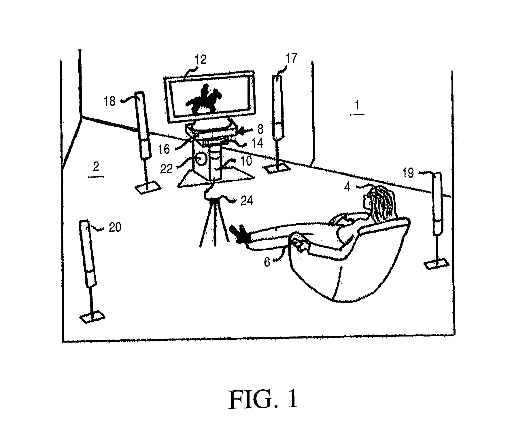
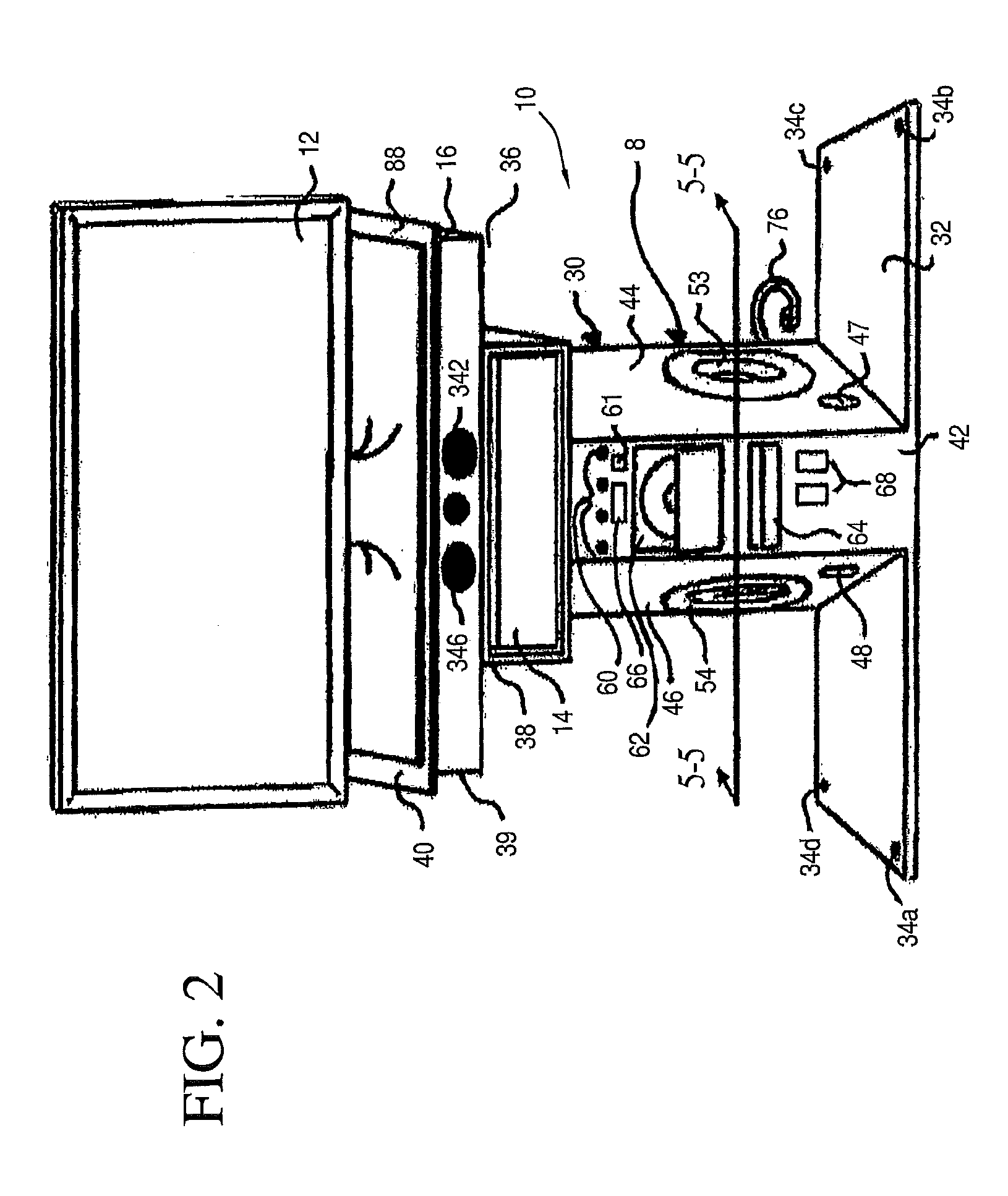
[0043]Referring to illustrative FIGS. 1-26, a home entertainment environment 1 located in a room 2 is described in general with respect to FIG. 1. A user 4 may utilize a remote control unit 6 to control operation. The home entertainment environment 1 comprises the apparatus, which creates an entertainment experience for the user 4. The home entertainment environment 1 comprises a home entertainment system 10 and may comprise a video display 12. The video display 12 may be part of a television set including tuners and an amplifier. Alternatively, the video display 12 could comprise a video monitor. The home entertainment system 10 is housed in a modular base 8 or pedestal enclosure 30. The home entertainment system 10 comprises components which provide different functions and which are integrated. Particular modules in the home entertainment unit 10 are described in further detail with respect to FIGS. 5 and 6. At the present time, commonly provided components include a radio tuner, ...


PUM


Abstract

A multi-channel loudspeaker enclosure and display support stand incorporates left speaker system and right speaker system integrally in a winged center channel enclosure 16. The multi-channel “winged” loudspeaker system enclosure includes a plurality of loudspeaker drivers mounted within baffles defining a plurality of compartments or sub-enclosures. The loudspeaker system enclosure has “wings” projecting laterally from a central pedestal support. The wings define bottom surfaces which provide a virtually invisible location for down-firing left and right side mid-bass drivers 601, 620, 640 (see, e.g., FIG. 12). In the multi-channel “winged” loudspeaker system of the present invention, the center channel speaker units, left channel speaker units and right channel speaker units each include one or more speaker drivers configured and driven to provide superior acoustic summation with the down-firing midbass drivers and with an optional subwoofer placed in a separate enclosure configured as a pedestal support.

Description

[0001]This application is a continuation-in-part of and claims priority to (a) commonly owned provisional patent application No. 60 / 632,187 filed Jan. 6, 2005 and to (b) commonly owned utility patent application Ser. No. 11 / 325,485, entitled INTEGRATED ENTERTAINMENT SYSTEM WITH AUDIO MODULES filed January 2006, the entire disclosures of which are each incorporated herein by reference.BACKGROUND OF THE INVENTION[0002]1. Field of the Invention[0003]The present invention relates to audio and video home entertainment equipment typically configured for use in the home.[0004]2. Discussion of the Prior Art[0005]Many home entertainment enthusiasts have configured audio and video playback systems including several components stacked on or under shelves, stands, carts, cabinets or tables, and these components are usually connected to one another with many signal cables and power cords. A system configured in this way typically includes components for receiving, detecting and demodulating audi...

Claims


Application Information

Patent Timeline
IPC IPC(8): H04R5/02H04R1/32H04R1/26G06F3/16H04R1/02
CPCH04R5/02G06F3/162H04S3/00H04R1/26H04R1/323H04R1/026H04R1/345H04R2420/09H04R2499/15
Inventor BEAUCHAMP, TODD
Owner BEAUCHAMP TODD
Why Eureka
Try Eureka