Liquid crystal display device

Inactive Publication Date: 2016-08-25
TCL CHINA STAR OPTOELECTRONICS TECH CO LTD
View PDF8 Cites 2 Cited by
  • Summary
  • Abstract
  • Description
  • Claims
  • Application Information

AI Technical Summary

Benefits of technology

[0020]Compared with the prior art, the present disclosure has the following advantages. The plurality of first protrusions and the plurality of second protrusions are arranged between the first substrate and the second substrate, wherein each of the plurality of first protrusions comprises the first upper portion and the first lower portion, while each of the plurality of the second protrusion comprises the second upper portion and the second lower portion. This enables

Problems solved by technology

However, the liquid crystal display 100 of such a structure also has certain defects.
For instance, because the spacers 94 and the protrusions 85 can provide poor bearing forces

Method used


Image

  • Liquid crystal display device
  • Liquid crystal display device
  • Liquid crystal display device

Examples


Example

[0027]In the drawings, the same components are indicated with the same reference signs. The figures are not drawn in accordance with an actual scale.

DETAILED DESCRIPTION OF THE EMBODIMENTS

[0028]The present disclosure will be further explained in conjunction with the accompanying drawings.

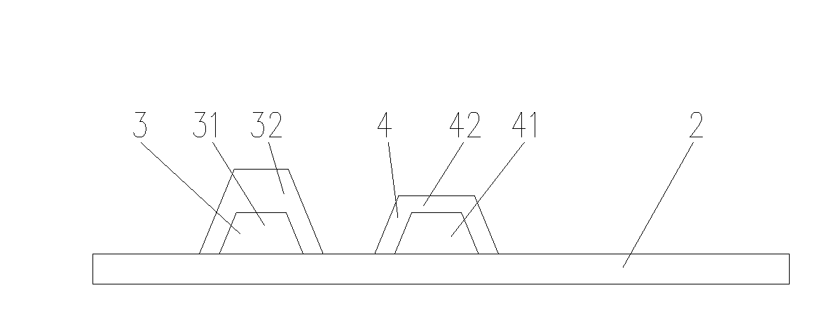
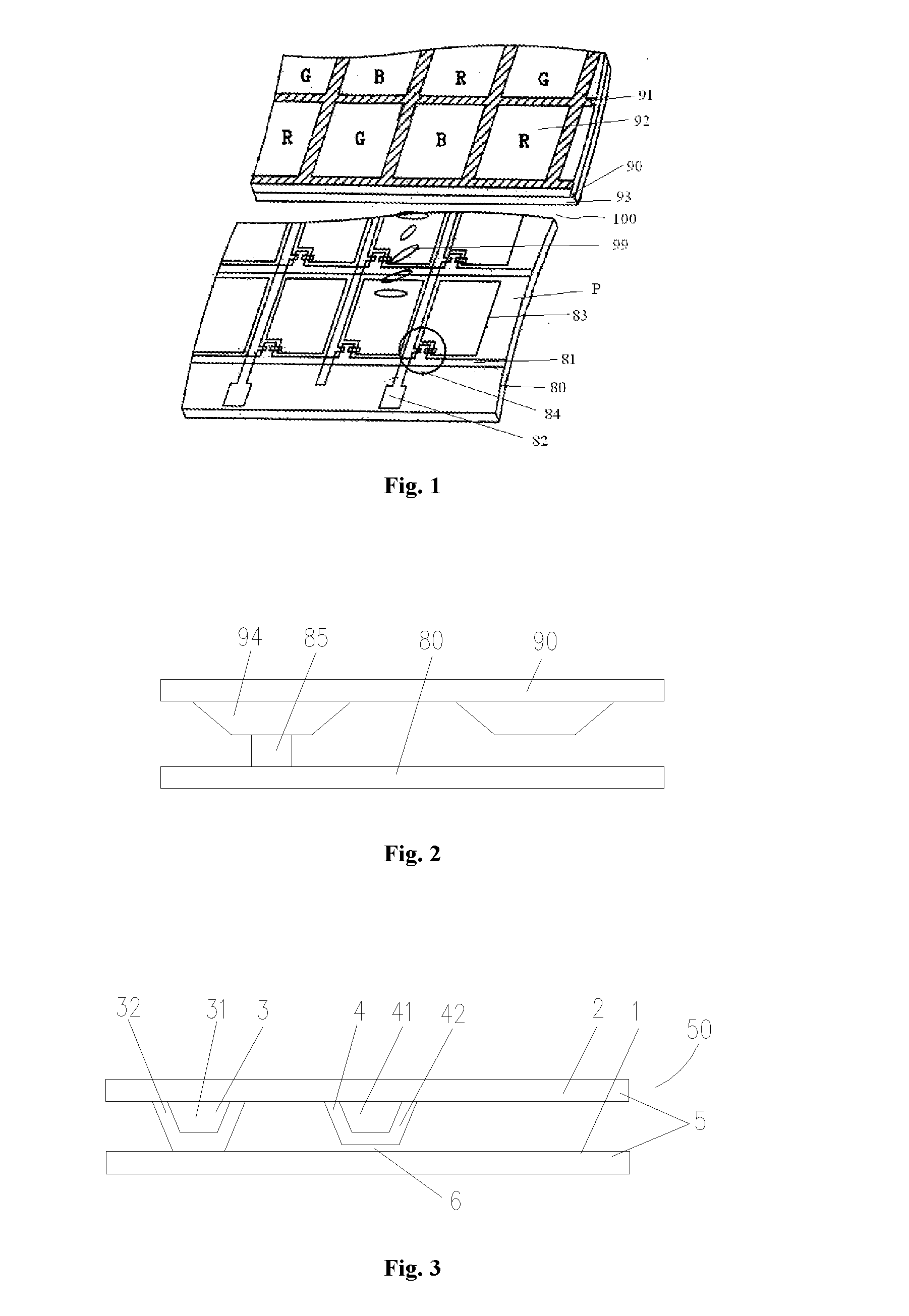
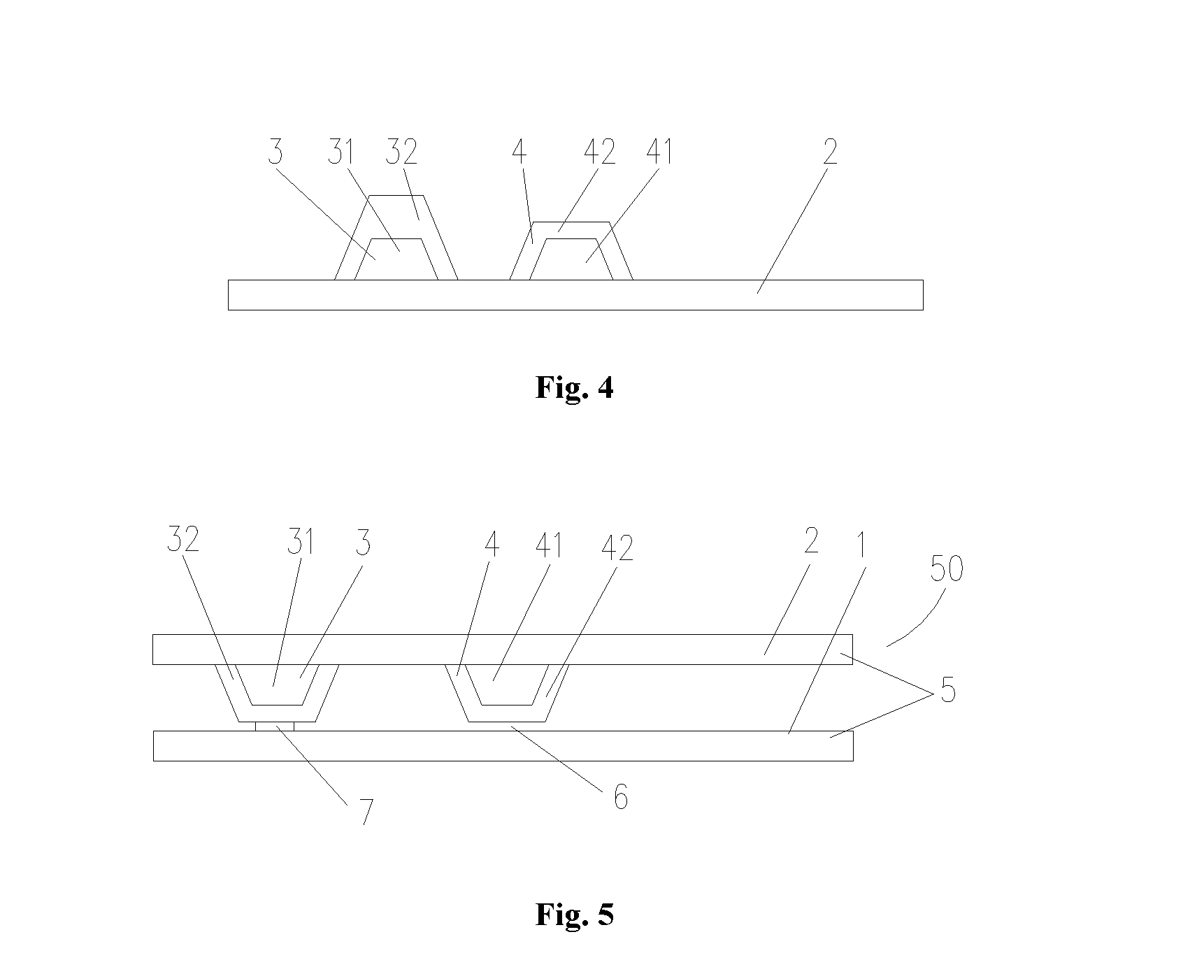
[0029]FIG. 3 schematically shows a cross-section view of a liquid crystal display device 50 according to one embodiment of the present disclosure. As indicated in FIG. 3, the liquid crystal display device 50 comprises a first substrate 1, a second substrate 2, a plurality of first protrusions 3, and a plurality of second protrusions 4. In a second state when the first substrate 1 and the second substrate 2 are assembled, the first substrate 1 and the second substrate 2 are arranged opposite to each other. In order to define a space between the first substrate 1 and the second substrate 2, the plurality of first protrusions 3 and the plurality of second protrusions 4 are located between the first sub...


PUM


Abstract

Disclosed is a liquid crystal display device, comprising a first substrate, a second substrate arranged opposite to the first substrate in a second state, a plurality of first protrusions arranged on the second substrate, and a plurality of second protrusions. Each of the plurality of first protrusions has a first lower portion which is made of a rigid material and arranged adjacent to a fixed end thereof, and a first upper portion which is made of an elastic material and arranged away from the fixed end thereof, wherein the plurality of first protrusions is pressed in the second state. The plurality of second protrusions is arranged on the second substrate and/or the first substrate. Each of the plurality of second protrusions has a second upper portion which is made of an elastic material and arranged away from a fixed end thereof, and a second lower portion which is made of a rigid material and arranged adjacent to the fixed end thereof, wherein in the second state, an interval is formed between a surface of the second upper portion and an inner surface of the first substrate or the second substrate opposite thereto. The liquid crystal display device has superior dynamic pressure resistance ability and a large allowable range for filling amount of liquid crystals.

Description

CROSS-REFERENCE TO RELATED APPLICATIONS[0001]The present application claims benefit of Chinese patent application CN 201410804223.3, entitled “Liquid crystal display device” and filed on Dec. 19, 2014, the entirety of which is incorporated herein by reference.FIELD OF THE INVENTION[0002]The present disclosure relates to a display device, and in particular, to a liquid crystal display device.BACKGROUND OF THE INVENTION[0003]With rapid development of the photoelectric technology develops, liquid crystal displays having the features of small sizes, light weight, superior display effects, and the like are increasingly popular among consumers.[0004]FIG. 1 shows a perspective view of a liquid crystal display in the prior art. As indicated in FIG. 1, a liquid crystal display 100 comprises a lower substrate 80, an upper substrate 90, and a liquid crystal layer 99 arranged between the upper substrate 90 and the lower substrate 80. The lower substrate 80 comprises a plurality of scan lines 81...

Claims


Application Information

Patent Timeline
IPC IPC(8): G02F1/1339G02F1/1362G02F1/1335
CPCG02F1/1339G02F1/133514G02F2001/13398G02F1/136286G02F2001/13396G02F1/13394G02F1/13392G02F1/13398G02F1/13396
Inventor TANG, YUEJUN
Owner TCL CHINA STAR OPTOELECTRONICS TECH CO LTD
Why Eureka
Try Eureka