Backlight module and liquid crystal display apparatus

Active Publication Date: 2013-09-12
TCL CHINA STAR OPTOELECTRONICS TECH CO LTD
View PDF3 Cites 2 Cited by
  • Summary
  • Abstract
  • Description
  • Claims
  • Application Information

AI Technical Summary

Benefits of technology

[0023]Compared with the conventional technology, in the present invention, the hollow structures are formed in the light guide plate corresponding to the light sources, and the hollow structures comprise two air layers with an included angle there-between, and the two air layers are a first hollow layer and a second hollow laye

Problems solved by technology

Concerning the normally incident light, when a light mixing distance d is constant, and the angle θLGP is reduced, the light rays will b

Method used


Image

  • Backlight module and liquid crystal display apparatus
  • Backlight module and liquid crystal display apparatus
  • Backlight module and liquid crystal display apparatus

Examples


Example

[0031]The following embodiments are exemplified by referring to the accompanying drawings, for describing specific embodiments implemented by the present invention.

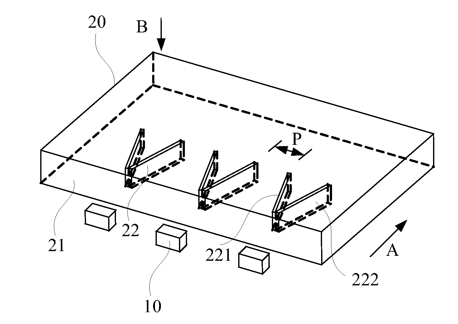
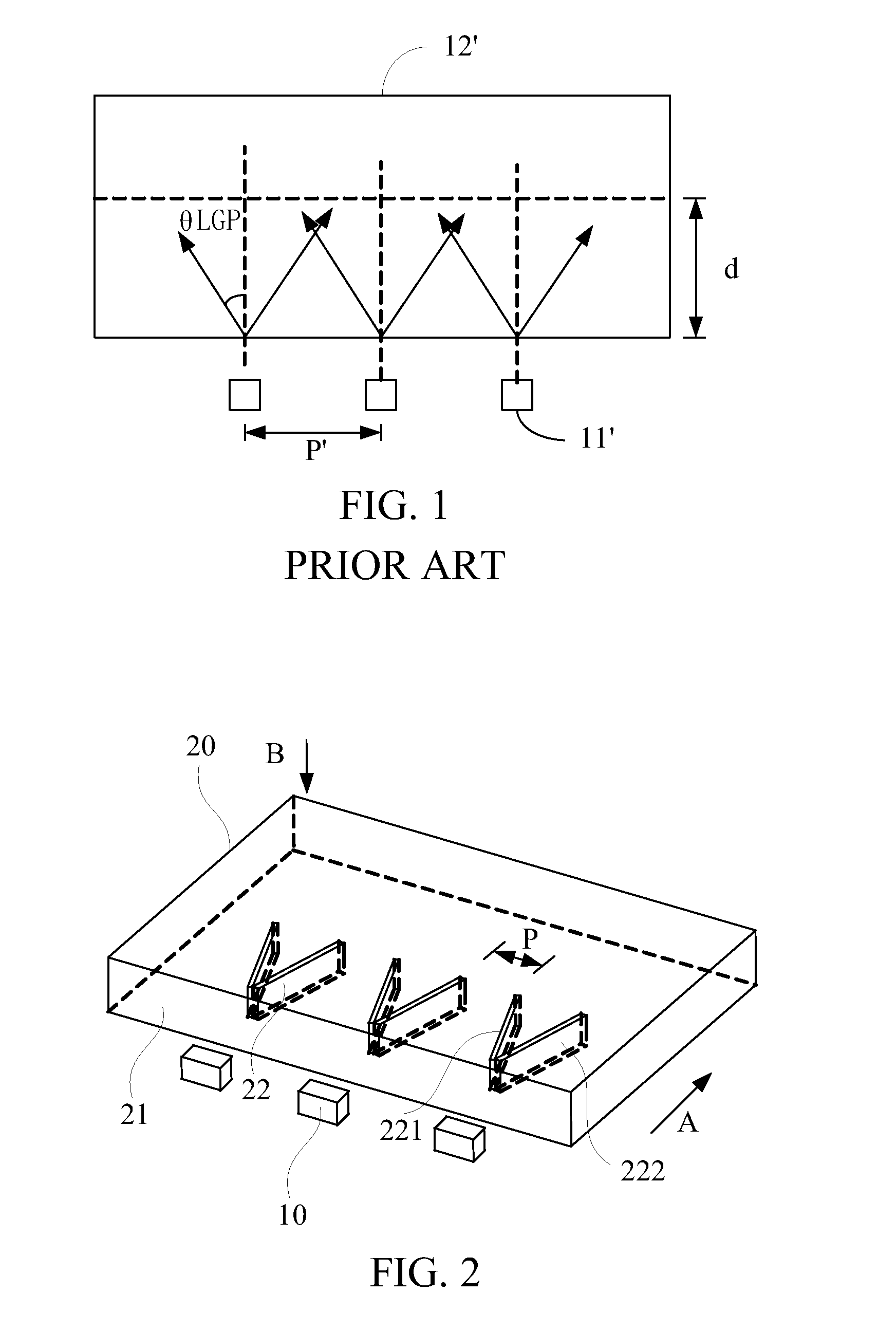
[0032]Referring to FIG. 2, FIG. 2 is a structural diagram showing a backlight module according to a first preferred embodiment of the present invention.

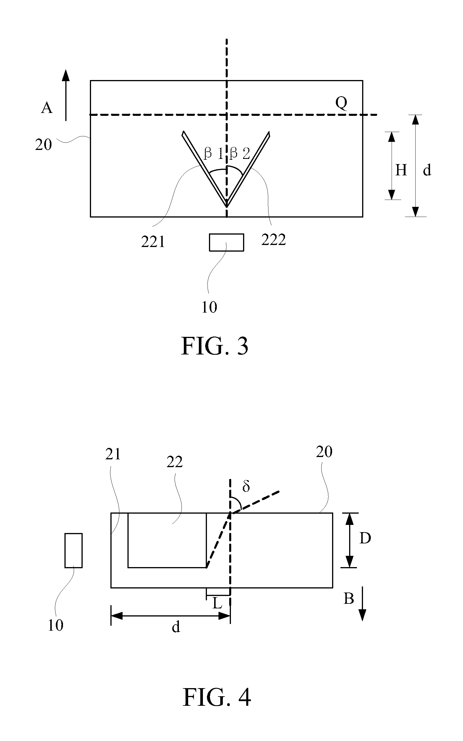
[0033]The backlight module comprises light sources 10 and a light guide plate 20. The light guide plate 20 includes a light-incident surface 21 and hollow structures 22 disposed therein. The hollow structures 22 comprise a first hollow layer 221 and a second hollow layer 222 disposed opposite thereto.

[0034]In the first preferred embodiment, as shown in FIG. 2, the first hollow layer 221 and the second hollow layer 222 have an included angle there-between, and are hollow plane layers with air layers therein. The first hollow layer 221 and the second hollow layer 222 are vertical to a light emitting surface and parallel to a thickness direction B of the light guide plate 20....


PUM


Abstract

The present invention provides a backlight module and a liquid crystal display apparatus. A light guide plate of the backlight module comprises hollow structures. The hollow structures correspond to the light sources and comprise two air layers with an included angle there-between, and the two air layers are a first hollow layer and a second hollow layer. A normal direction is vertical to the light-incident surface, and there is a first oblique angle between the first hollow layer and the normal direction, and there is a second oblique angle between the second hollow layer and the normal direction. The present invention can prevent the problem of uneven brightness distribution.

Description

FIELD OF THE INVENTION [0001]The present invention relates to a field of a liquid crystal display (LCD) technology, and more particularly to a backlight module and a liquid crystal display apparatus.BACKGROUND OF THE INVENTION [0002]In accordance with a development of lightening and thinning LCDs, an amount of light emitting diodes (LEDs) required for backlight is reduced.[0003]Referring to FIG. 1, in a side-light type backlight module, the amount of the LEDs is reduced, resulting in an increase of a distance P′ between the LEDs. Since a density of a light guide plate 12′ is different to a density of air, normally less than the density of air, a refraction of light rays arises when the light rays are emitted from the LEDs 11′ into the light guide plate 12′.[0004]When the light rays are emitted form the LEDs 11′, a portion of the light rays is normally incident to the light guide plate 12′, and the normally incident light rays have an angle θair of 90 degrees. When entering the light...

Claims


Application Information

Patent Timeline
IPC IPC(8): G02F1/13357F21V8/00
CPCG02B6/0073G02B6/0068
Inventor ZHOU, GEGEFANG, KUOJUN
Owner TCL CHINA STAR OPTOELECTRONICS TECH CO LTD
Why Eureka
Try Eureka