Cylinder Head Gasket

a technology of cylinder head and gasket, which is applied in the direction of engine seals, machine/engines, engine sealing arrangements, etc., can solve the problems of increasing the movement of the cylinder head relative to the engine block, and achieve the effect of improving the fluid tight seal

Inactive Publication Date: 2016-09-01
FEDERAL MOGUL MOTORPARTS LLC
View PDF0 Cites 4 Cited by
  • Summary
  • Abstract
  • Description
  • Claims
  • Application Information

AI Technical Summary

Benefits of technology

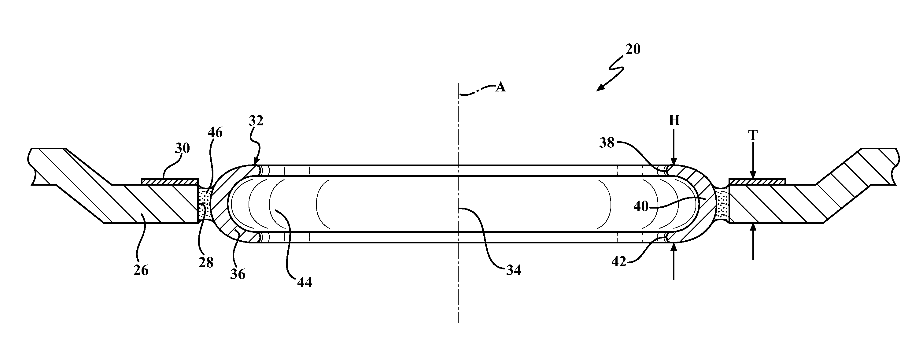
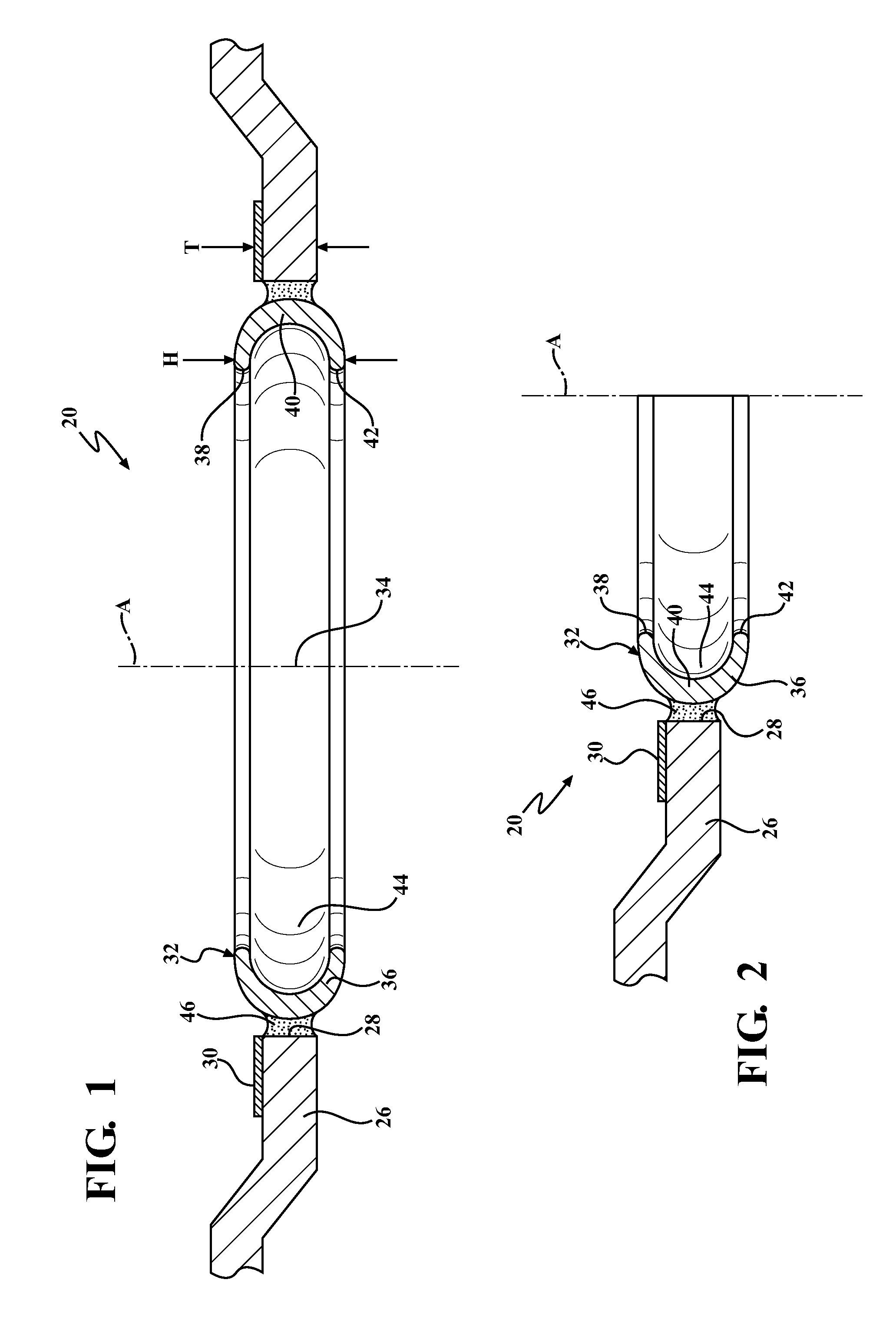
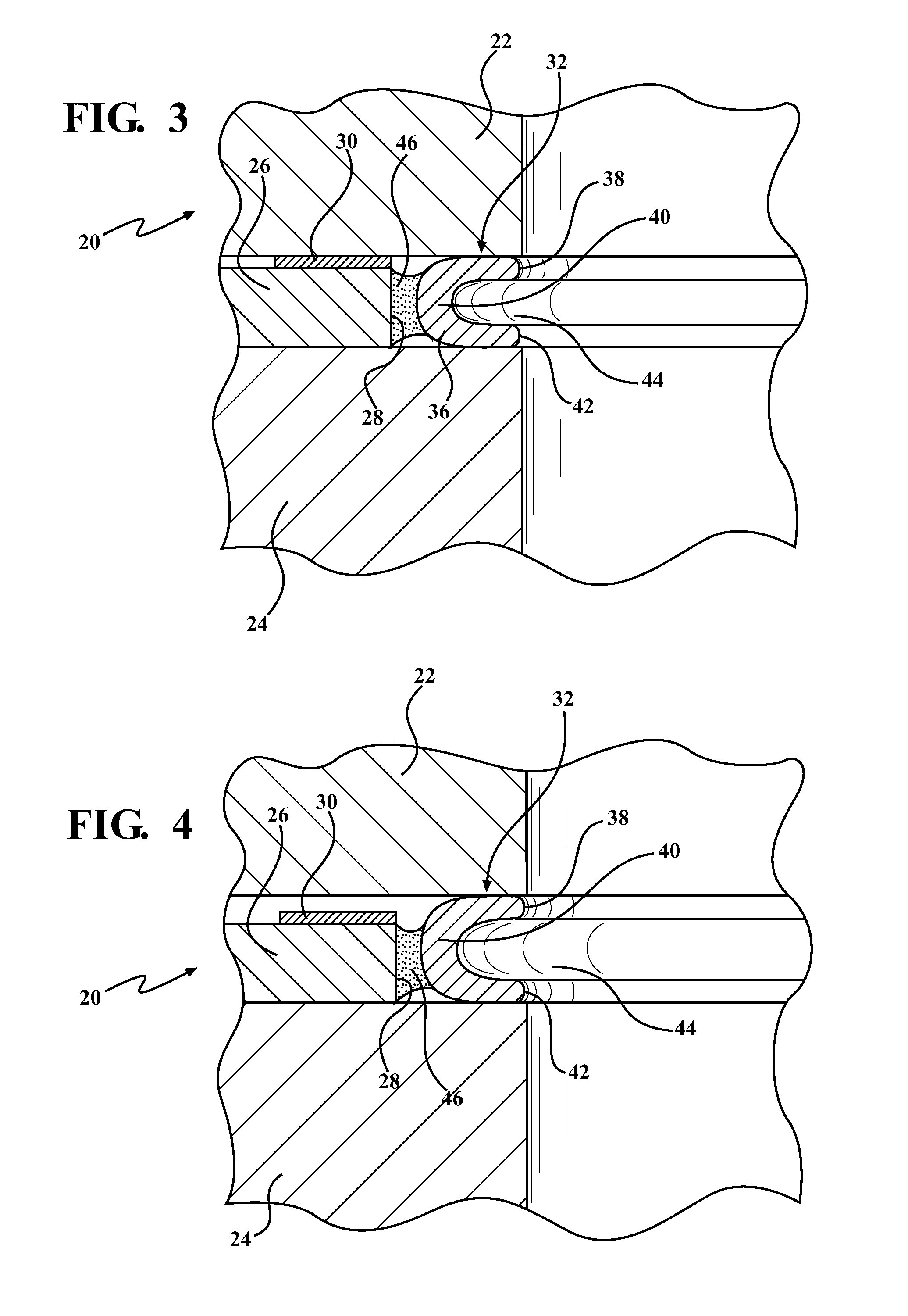
[0006]One aspect of the present invention is related to an improved cylinder head gasket for establishing a fluid tight seal between a cylinder head and an engine block of an internal combustion engine. The cylinder head gasket includes a gasket layer which presents at least one inner periphery that surrounds at least one opening. The gasket layer has a first thickness adjacent the inner periphery. A combustion seal is positioned in the opening and extends circumferentially around an axis between ends that are joined together. The combustion seal is joined with the inner periphery of the gasket layer. The combustion seal has a height in a direction parallel to the axis, and the height is greater than the first thickness of the gasket layer. The combustion seal includes at least one seal body which is generally C-shaped as viewed in cross-section and is resiliently flexible for maintaining fluid tight seals with the cylinder head and the engine block during operation of the engine. The C-shaped seal body presents a pocket which faces away from the inner periphery of the of the gasket layer for receiving combustion gasses during use to improve the fluid tight seals established with the cylinder head and the engine block.

Problems solved by technology

During operation of the engine, this may result in increased movement of the cylinder head relative to the engine block as the combustion of a fuel and air mixture within a plurality of cylinder bores tends to energize the cylinder head away from the engine block.

Method used


Image

  • Cylinder Head Gasket
  • Cylinder Head Gasket
  • Cylinder Head Gasket

Examples


Embodiment Construction

[0018]Referring to the Figures, wherein like numerals indicate corresponding parts throughout the several views, a first exemplary embodiment of a cylinder head gasket 20 is generally shown in FIGS. 1-4. As shown in FIGS. 3 and 4, the cylinder head gasket 20 is configured for providing a fluid tight seal between a cylinder head 22 and an engine block 24 of an internal combustion engine to seal combustion and exhaust gasses in one or more cylinder bores during operation of the engine. For the purposes of simplicity, the term “engine block” as used herein also includes one or more cylinder liners (also known as sleeves) for engines that include cylinder liners. The cylinder head gasket 20 may find uses in a range of different types of piston driven internal combustion engines including, for example, two or four stroke engines and gasoline or diesel fueled engines.

[0019]Referring to FIG. 1, the exemplary cylinder head gasket 20 includes a single gasket layer 26 with a plurality of inne...


PUM


Abstract

The cylinder head gasket includes a gasket layer which presents an inner periphery that surrounds an opening. The gasket layer has a first thickness adjacent the inner periphery. A combustion seal is positioned in the opening and extends circumferentially around an axis. The combustion seal is joined with the inner periphery of the gasket layer. The combustion seal has a height that is greater than the first thickness of the gasket layer. The combustion seal includes at least one seal body which is generally C-shaped as viewed in cross-section and is resiliently flexible for maintaining fluid tight seals with the cylinder head and the engine block. The C-shaped seal body presents a pocket which faces away from the inner periphery of the of the gasket layer for receiving combustion gasses during use to improve the fluid tight seals established with the cylinder head and the engine block.

Description

BACKGROUND OF THE INVENTION[0001]1. Field of the Invention[0002]The present invention is directed to cylinder head gaskets for establishing a fluid-tight seal between an engine block and a cylinder head of a piston driven internal combustion engine.[0003]2. Related Art[0004]In a continuing effort to improve fuel economy while improving or at least maintaining power output, engine manufacturers have increasingly been employing advanced technologies, such as direct injection, turbochargers and superchargers. One common effect of these advanced technologies is increased combustion pressures and temperatures. During operation of the engine, this may result in increased movement of the cylinder head relative to the engine block as the combustion of a fuel and air mixture within a plurality of cylinder bores tends to energize the cylinder head away from the engine block. It is important for the cylinder head gasket to maintain a fluid tight seal during the lifting movement of the cylinder...

Claims


Application Information

Patent Timeline
Patent Type & Authority Applications(United States)
IPC IPC(8): F02F11/00
CPCF16J2015/0862F16J2015/085F02F11/002F16J2015/0875F16J15/0818F02F2200/00
Inventor SWASEY, THOMAS W.MAGEWICK, CHRISTRIPATHY, BHAWANI
Owner FEDERAL MOGUL MOTORPARTS LLC
Why Eureka
Try Eureka