Building Profile

a building profile and profile technology, applied in the field of building profiles, can solve the problems of difficult for a single builder to hold the stakes, difficult for a single builder to transport and carry, and laborious and time-consuming erection of building profiles, etc., to achieve convenient and efficient removal, convenient and convenient disassembly of building profiles for storage and reuse.

Active Publication Date: 2016-09-01
EZYPROFILE SYST
View PDF9 Cites 12 Cited by
  • Summary
  • Abstract
  • Description
  • Claims
  • Application Information

AI Technical Summary

Benefits of technology

[0010]Advantageously, the cross member can be conveniently fastened to the support legs by a single builder without the need for additional tools such as nails and hammers. In addition, the cross member can be conveniently and efficiently removed to disassemble the building profile for storage and reuse.

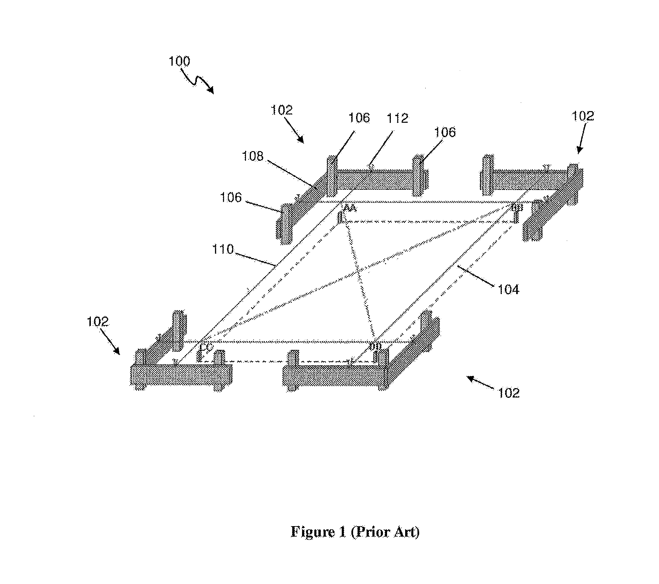
Problems solved by technology

When erecting conventional building profiles 102, it can often be difficult for a single builder to hold the stakes 106 and timber 108 in their correct positions before securing them to each other using a hammer and nails.
Consequently, in many constructions sites, at least two builders would be required when erecting profiles, thus making the erection of building profiles 102 labour intensive and time consuming.
Moreover, a large number of stakes and timber planks may be required for a construction site, which can be heavy and bulky, thus making it difficult for a builder to transport and carry.

Method used


Image

  • Building Profile
  • Building Profile
  • Building Profile

Examples


Embodiment Construction

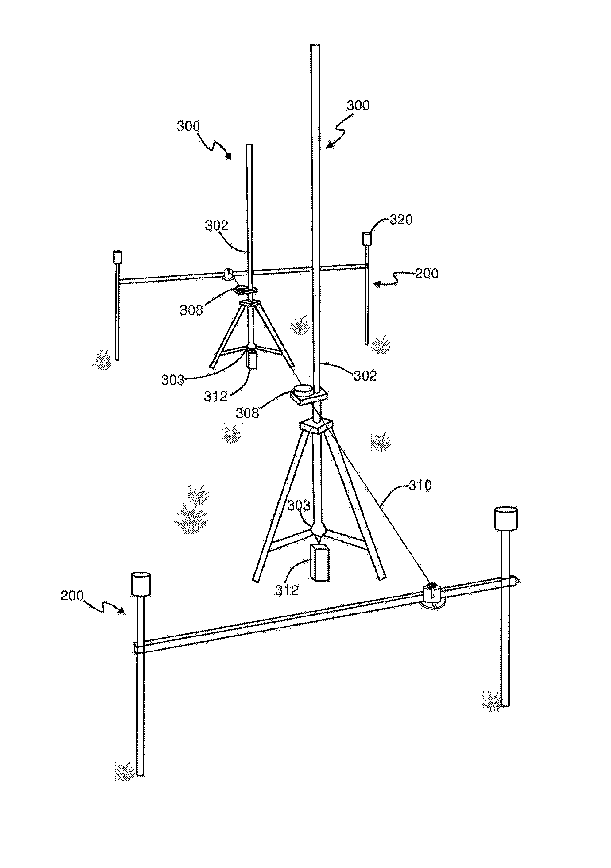
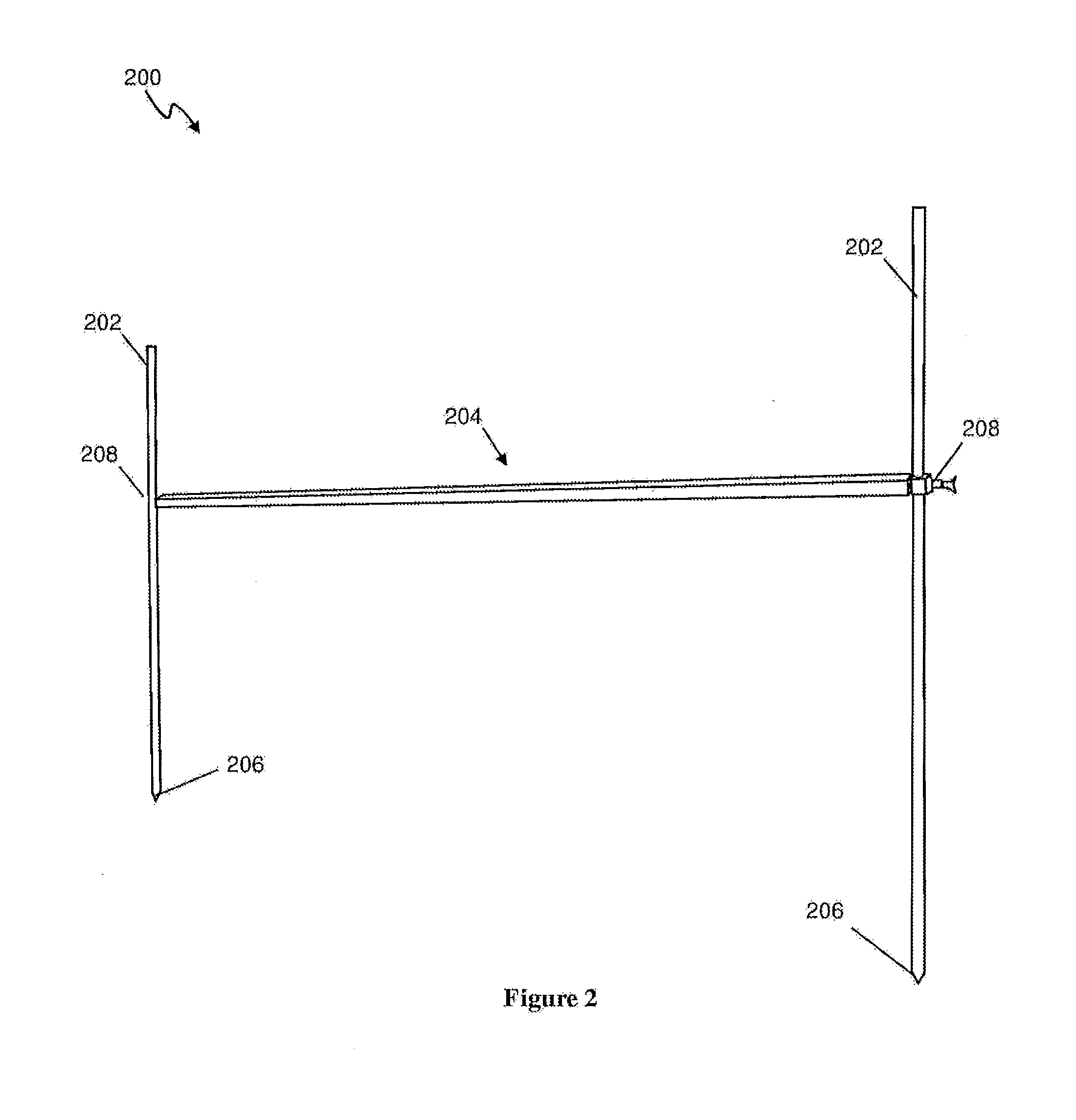
[0039]FIG. 2 illustrates a building profile 200 according to an embodiment of the present invention. The building profile 200 includes a pair of stakes (support legs) 202 and a rail (cross member) 204. Each stake 202 has a pointed end 206 to facilitate driving the stake 202 into the ground. Clamps 208 are located proximate each end of the rail 204 for removably fastening the rail 204 between the pair of stakes 202.

[0040]As illustrated in further detail in FIG. 3, each clamp 208 includes a sleeve 210, and a screw 214 for securing a respective stake 202 within the sleeve 210. Elaborating further, the sleeve 210 is sized to receive and sliding along a respective stake 202. Once the sleeve 210 is moved to a desired location on the stake 202, the screw is turned in one direction to engage with the stake 202 such that the stake 202 is clamped between an inner end of the screw 214 and an internal wall of the sleeve 210. To release the stake 202 from the clamp 208, the screw 214 is turned i...


PUM


Abstract

The present invention is directed to a building profile including a pair of support legs, a cross member for removably fastening to the pair of support legs and from which a line can extend; a marker stand for engaging with the line, wherein the marker stand includes a point position marker for marking a position on the ground, a support for supporting the point position marker and an upright indicator for indicating whether the point position marker is in an upright position.

Description

TECHNICAL FIELD[0001]The present invention relates to a building profile.BACKGROUND ART[0002]During construction, boundaries and positions within a construction site are initially marked out using string (reference lines). These boundaries and positions can include the boundaries and positions of all foundations for external and internal walls, positions of sewerage pipes, entry points for power supply and the like. Typically, building profiles are first set up around the construction site to roughly mark out the construction area. Then strings are tied to the building profiles to mark out the specific boundaries and positions.[0003]FIG. 1 illustrates a conventional construction site 100 in which building profiles 102 are used to mark out the boundaries and position for a proposed foundation 104. To erect each building profile 102, two or more stakes 106 are first driven into the ground. Then, a plank of timber 108 is attached between adjacent stakes 106 using nails. Once the approp...

Claims


Application Information

Patent Timeline
Patent Type & Authority Applications(United States)
IPC IPC(8): G01C15/06E04G21/00G01C15/10
CPCG01C15/06E04G21/00G01C15/10E04G21/1833F16M11/32
Inventor EGAN, MICHAEL KENNETH
Owner EZYPROFILE SYST
Why Eureka
Try Eureka