
Infusion fluid warmer

a technology for infusion fluid and warmer, which is applied in the direction of heating element materials, medical devices, heating element shapes, etc., can solve the problems of unsuitable portable applications, difficult or impossible to secure or attach the fluid to the patient's body in a convenient and safe manner, and the conventional device and technique suffers from a number of drawbacks, so as to minimize the risk of accidental detachment and simplify the fluid delivery process

Active Publication Date: 2017-12-21
MEQU
View PDF7 Cites 0 Cited by
  • Summary
  • Abstract
  • Description
  • Claims
  • Application Information

AI Technical Summary

Benefits of technology

The patent describes an infusion fluid warmer that can be used to heat fluids like blood for medical purposes. The warmer is designed to be portable and easy to use in emergency situations or in war zones. The portable energy source is enclosed in an insulating and thermally conducting housing, and the fluid channel around the energy source is designed to maximize heat transfer and cool the energy source efficiently. The warmer can be attached to the patient's body for direct fluid delivery, making it convenient and minimizing the risk of detachment. The technical effects of this invention are a portable, efficient, and easy-to-use infusion fluid warmer for medical purposes.

Problems solved by technology

However, these conventional devices and techniques suffer from a number of drawbacks.
The conventional infusion fluid warmers are bulky and heavy which make them unsuited for portable applications where they have to be transported by foot for example by soldiers, rescue workers or ambulance crews to reach inaccessible emergency sites.
The heavy and bulky nature of existing infusion fluid warmers also makes it difficult or impossible to secure or attach these to the patient's body in a convenient and safe manner.
Another disadvantage of existing fluid warmers is that they are composed of a large number of separate parts which make them expensive to manufacture and tend to reduce reliability due to a multitude of separate engaging parts.
Yet another disadvantage of existing fluid warmers is a lack of a mechanism for capturing and coupling heat energy dissipated in the energy source during fluid warming to the infusion fluid.
This leads to inefficient use of energy stored in the energy source, such as rechargeable or non-rechargeable batteries, and therefore a need for larger, heavier and more costly energy sources than strictly required to warm a given volume or amount of infusion fluid.

Method used


Image

  • Infusion fluid warmer
  • Infusion fluid warmer
  • Infusion fluid warmer

Examples


first embodiment

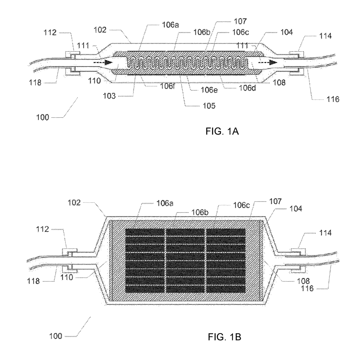
[0034]FIG. 1a) shows a vertical cross-sectional view of an infusion fluid warmer 100 in accordance with the invention. The infusion fluid warmer 100 comprises a housing shell 104 formed in a thermally conducting and electrically insulating material, preferably comprising a ceramic material such as Aluminium Oxide (Al.sub.2O.sub.3). The dimensions of the housing shell 104 may vary in accordance with specific requirements for the infusion fluid warmer 100, in particular its fluid warming capacity.

[0035]The housing shell 104 is encapsulated or enclosed within an outer casing 102 which may be formed in a suitable polymeric material for example a thermoplastic material or elastomeric compound by injection moulding. The outer casing 102 may be shaped and sized to protect the housing shell 104 from mechanical shocks and impacts. A pair of cap nuts or caps 112, 114 covers respective entrance openings of the outer casing 102 and is preferably used to seal or isolate the interior volume of th...

embodiment 100

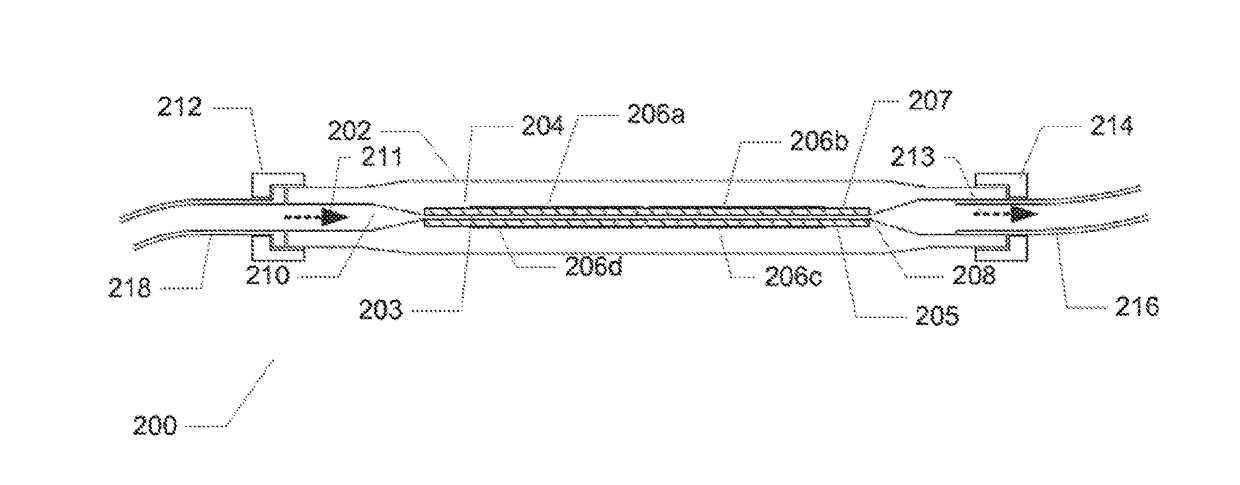
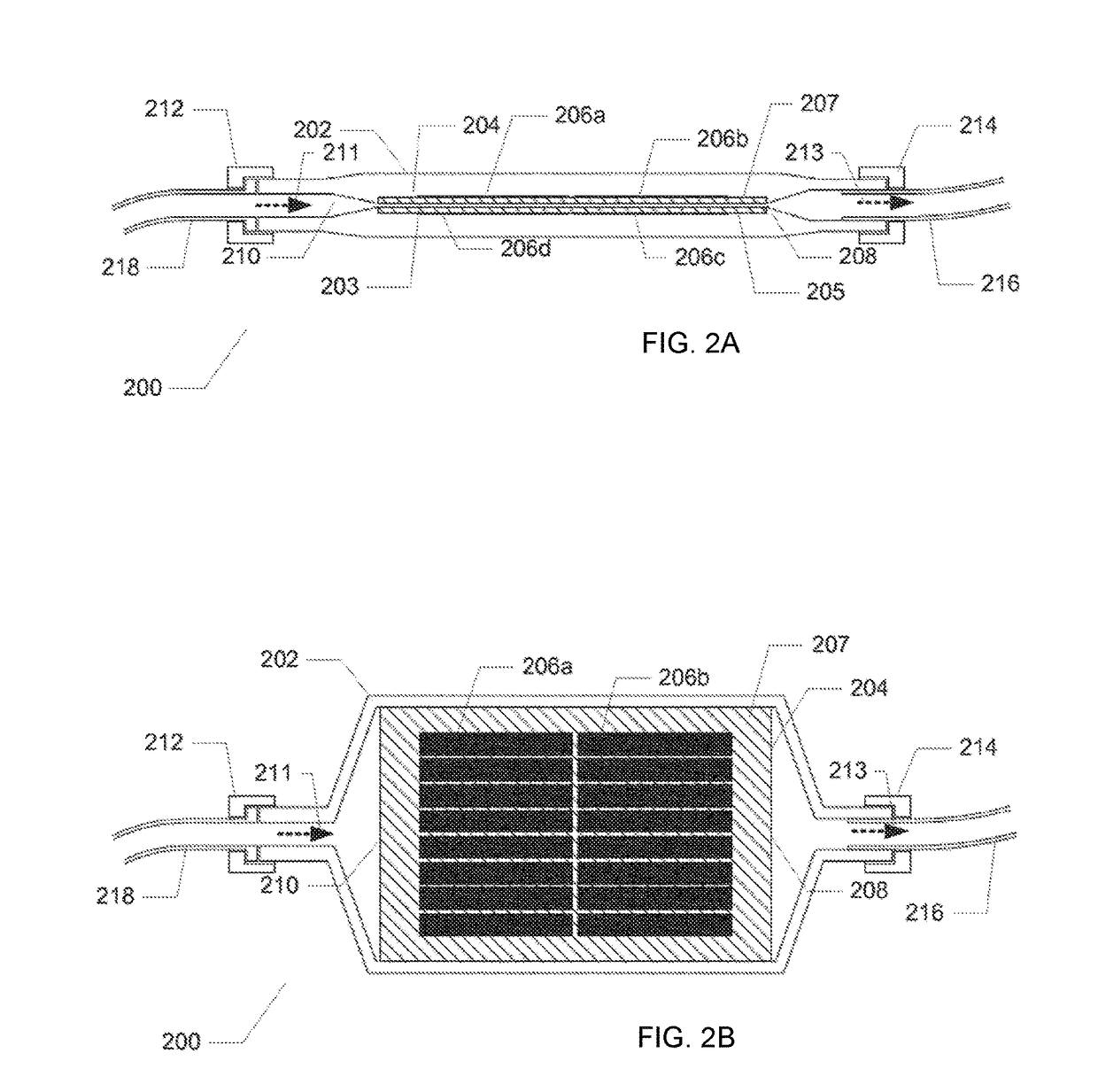
[0043]The infusion fluid warmer 200 may comprise a temperature sensor (not shown) for determining a temperature of the infusion fluid in the fluid channel 203 for example at the outlet port 208. The temperature sensor may be utilized to ascertain the infusion fluid temperature lies within a certain allowable range for example between 36 and 37 degree Celsius. A controller circuit (not shown) is operatively coupled to the temperature sensor and to the array of thick film resistors 206a-206d to control instantaneous power dissipation in the array in the same manner as described above in connection with the first infusion fluid warmer embodiment 100.

[0044]The skilled person will appreciate the firm bonding between the array of thick film resistors 206a-206d and the housing shell 204 provides a compact unitary assembly of heating element and heat exchanger with a low parts count in the present infusion fluid warmer 200.

second embodiment

[0045]FIG. 2b) shows a top view of the infusion fluid warmer 200 in accordance with the invention. The lid or upper wall of the thermoplastic casing 202 has been removed such that the outer surface of the upper wall 207 of the housing shell 204 is exposed. The thick film resistors 206a, 206b are disposed on the outer surface of the upper wall 207 covering a large portion of the available surface area. Each of the thick film resistors 206a, 206b comprises a plurality of individual resistor segments arranged in width wise direction. These resistor segments may be coupled in series or parallel to provide a desired resistance value of the thick film resistor in question.

[0046]FIG. 2c) illustrates a vertical cross-sectional view of an infusion fluid warmer 250 in accordance with a third embodiment of the invention. Similar features and elements of the present embodiment and the above-described second embodiment of the infusion fluid warmer have been provided with corresponding reference ...


PUM


Abstract

The present invention relates in one aspect to an infusion fluid warmer which comprises a casing shell having an upper wall structure and a lower, opposing, wall structure. The casing shell encloses a fluid channel or passage extending through the casing shell in-between the upper and lower wall structures and fluid inlet and outlet ports coupled to opposite ends of the fluid channel or passage to allow a flow of infusion fluid through the casing shell. A housing shell is formed in a thermally conducting and electrically insulating material and a heating element is bonded to the housing shell and thermally coupled thereto. The fluid channel or passage extends through the housing shell or extends around the housing shell such that heat energy is transferred to the infusion fluid by direct physical contact with housing shell material.

Description

CROSS-REFERENCE TO RELATED APPLICATIONS[0001]This application is a divisional of U.S. patent application Ser. No. 14 / 351,388, filed Apr. 11, 2014, entitled, “INFUSION FLUID WARMER”, which is a national stage entry of PCT Application PCT / EP2012 / 069887, filed Oct. 8, 2012, entitled “AN INFUSION FLUID WARMER”, which claims the benefit of U.S. Provisional Patent Application Ser. No. 61 / 546,779, Oct. 13, 2011, entitled “AN INFUSION FLUID WARMER,” all of which are incorporated by reference herein in their entireties.[0002]The present invention relates in one aspect to an infusion fluid warmer which comprises a casing shell having an upper wall structure and a lower, opposing, wall structure. The casing shell encloses a fluid channel or passage extending through the casing shell in-between the upper and lower wall structures and fluid inlet and outlet ports coupled to opposite ends of the fluid channel or passage to allow a flow of infusion fluid through the casing shell. A housing shell i...

Claims


Application Information

Patent Timeline
Patent Type & Authority Applications(United States)
IPC IPC(8): A61M5/44H05B3/20H05B3/16
CPCH05B2203/002H05B2203/021A61M5/44H05B3/16H05B3/20A61M5/445A61M2205/3368A61M2205/3653A61M2205/8206G05D23/2401H05B3/44H05B2203/013
Inventor ANDERSEN, ULRIK KROGH
Owner MEQU
Learn More