Maximized Power in a Photovoltaic Distributed Power System

a distributed power system and photovoltaic technology, applied in the direction of electrical equipment without intermediate ac conversion, ac network circuit arrangement, electrical equipment, etc., can solve the problems of overall reducing the reliability of the power harvesting system, adding to the cost, etc., to maximize the power harvested, efficient power optimization, and without incurring excessive costs

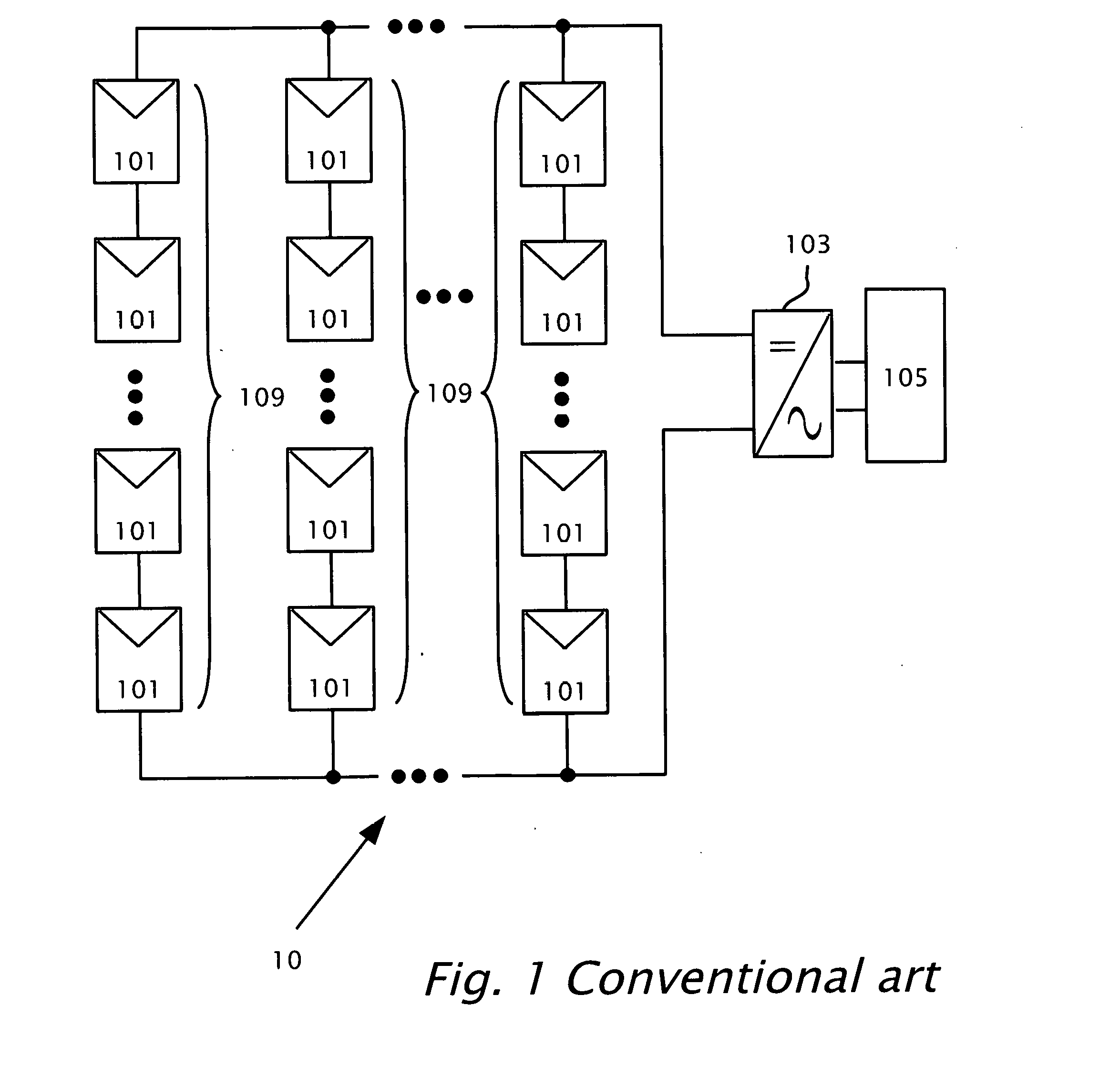
Active Publication Date: 2016-09-01
SOLAREDGE TECH LTD
View PDF4 Cites 27 Cited by
  • Summary
  • Abstract
  • Description
  • Claims
  • Application Information

AI Technical Summary

Benefits of technology

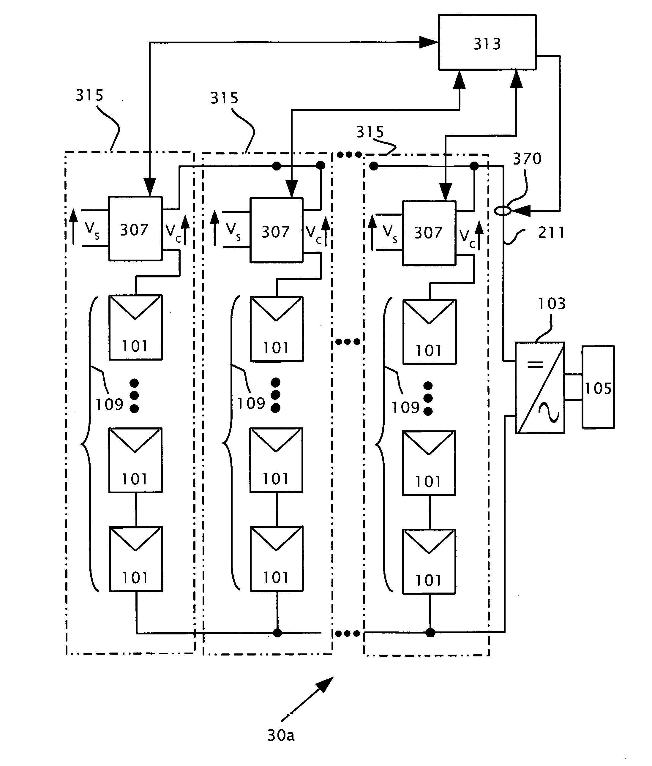
[0026]According to features presented there is provided a method in a power harvesting system which includes a photovoltaic string. The photovoltaic string may include a series-connection of photovoltaic panels. The method connects in series a voltage-compensation circuit within the photovoltaic string. A circuit parameter may be monitored within the photovoltaic string. A compensation voltage of the voltage-compensation circuit may be configured based on the monitoring. The compensation voltage may be added serially within the photovoltaic string, thereby maximizing the power harvested from the photovoltaic string. A DC load may be attached to the photovoltaic string. An input of the voltage-compensation circuit may be connected to either a source of AC power or a source of DC power. The circuit parameter may include a current produced by the photovoltaic string, a voltage across the photovoltaic string or the power produced by the photovoltaic string.
[0027]Embodiments herein may employ photovoltaic power systems including power voltage-compensation devices, which may be referred to as power balancing devices, to allow efficient power optimization for the systems without incurring excessive costs.
[0028]In some embodiments, PV power devices may be included in photovoltaic system design to increase the system power output.
[0029]In some embodiments, a sing...

Problems solved by technology

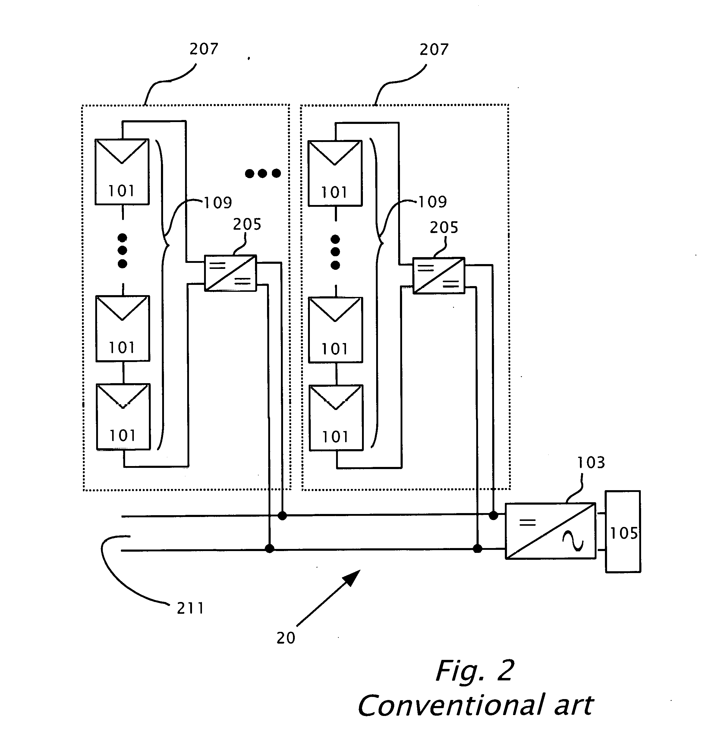
The high power DC-DC converters 205 in a power harvesting system may add to the cost of installation and maintenance of the power harvesting syste...

Method used


Image

  • Maximized Power in a Photovoltaic Distributed Power System
  • Maximized Power in a Photovoltaic Distributed Power System
  • Maximized Power in a Photovoltaic Distributed Power System

Examples


Embodiment Construction

[0062]In the following description of various illustrative embodiments, reference is made to the accompanying drawings, which form a part hereof, and in which is shown, by way of illustration, various embodiments in which aspects of the disclosure may be practiced. It is to be understood that other embodiments may be utilized and structural and functional modifications may be made, without departing from the scope of the present disclosure.

[0063]It should be noted, that although the discussion herein relates primarily to photovoltaic systems, the present invention may, by non-limiting example, alternatively be configured using other distributed power systems including (but not limited to) wind turbines, hydro turbines, fuel cells, storage systems such as battery, super-conducting flywheel, and capacitors, and mechanical devices including conventional and variable speed diesel engines, Stirling engines, gas turbines, and micro-turbines.

[0064]By way of introduction, features of the pr...


PUM


Abstract

A power harvesting system including multiple parallel-connected photovoltaic strings, each photovoltaic string includes a series-connection of photovoltaic panels. Multiple voltage-compensation circuits may be connected in series respectively with the photovoltaic strings. The voltage-compensation circuits may be configured to provide respective compensation voltages to the photovoltaic strings to maximize power harvested from the photovoltaic strings. The voltage-compensation circuits may be include respective inputs which may be connected to a source of power and respective outputs which may be connected in series with the photovoltaic strings.

Description

CROSS REFERENCE TO RELATED APPLICATIONS[0001]The present application is a continuation-in-part (CIP) application of U.S. application Ser. No. 13 / 754,059 filed Jan. 30, 2013, which claims priority to United Kingdom Application GB1201499.9, filed Jan. 30, 2012, all of which are incorporated herein by reference in their entirety.BACKGROUND[0002]Photovoltaic (PV) power devices can be used to improve the performance and to reduce the cost of power generation systems including photovoltaic panels. Photovoltaic power devices can be variously configured. The cost of some power devices may be proportional to the amount of electrical power they process. Thus, significant savings can be realized by designing systems to optimize output power while processing a small portion of the system power.[0003]Accordingly, there is a need for designing power device system with increased efficiency while decreasing the operating costs associated with such as system.[0004]1. Technical Field[0005]The exempla...

Claims


Application Information

Patent Timeline
IPC IPC(8): H02J3/38H02M7/44H02M3/04
CPCH02J3/383H02M7/44H02M3/04H02J2300/26H02J3/381Y02E10/56H02J3/46H02J3/38
Inventor YOSCOVICH, ILANBIEBER, OFIRGLOVINSKY, TZACHI
Owner SOLAREDGE TECH LTD
Why Eureka
Try Eureka